Multi-stage traveling wave thermoacoustic engine system for cascaded utilization of waste heat of high temperature flue gas

A thermoacoustic engine, high temperature flue gas technology, applied in the direction of machines/engines, mechanisms that generate mechanical power, mechanical equipment, etc., can solve problems such as singleness, reduce system complexity, reduce heat loss, and improve heat utilization efficiency , to achieve the effect of energy saving and emission reduction

Active Publication Date: 2015-08-26
TECHNICAL INST OF PHYSICS & CHEMISTRY - CHINESE ACAD OF SCI
View PDF5 Cites 7 Cited by
  • Summary
  • Abstract
  • Description
  • Claims
  • Application Information

AI Technical Summary

Problems solved by technology

[0008] In order to solve the problem of high-efficiency conversion and simple output of the variable-temperature heat source using flue gas waste heat in the traditional system, this invention proposes a new type of process, which can utilize heat sources of different temperature grades efficiently and in low steps, and simultaneously output adopts a single output , reducing system complexity

Method used


Image

  • Multi-stage traveling wave thermoacoustic engine system for cascaded utilization of waste heat of high temperature flue gas
  • Multi-stage traveling wave thermoacoustic engine system for cascaded utilization of waste heat of high temperature flue gas
  • Multi-stage traveling wave thermoacoustic engine system for cascaded utilization of waste heat of high temperature flue gas

Examples


Embodiment 1

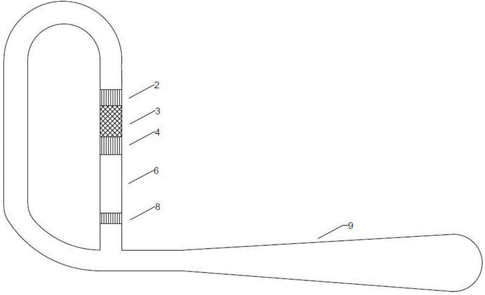
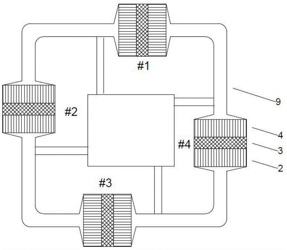
[0029] Figure 4 It is a structural schematic diagram of a multi-stage traveling wave thermoacoustic engine system (embodiment 1) for cascade utilization of high-temperature flue gas waste heat of the present invention. Such as Figure 4 As shown, the multi-stage traveling wave thermoacoustic engine system in this embodiment 1 consists of three stages (#1 thermoacoustic engine unit, #2 thermoacoustic engine unit and #3 thermoacoustic engine unit) with the same structure and different sizes of thermoacoustic The engine unit is composed of; the thermoacoustic engine units at all levels are connected end-to-end through resonance tubes 9 with different diameters to form a loop structure, and each level of thermoacoustic engine unit is in the traveling wave phase in the loop structure; each level of thermoacoustic The engine unit is composed of DC suppressor 1, main cooler 2, regenerator 3, heater 4, high temperature end laminar fluidization element 5, thermal buffer pipe 6, room ...

Embodiment 2

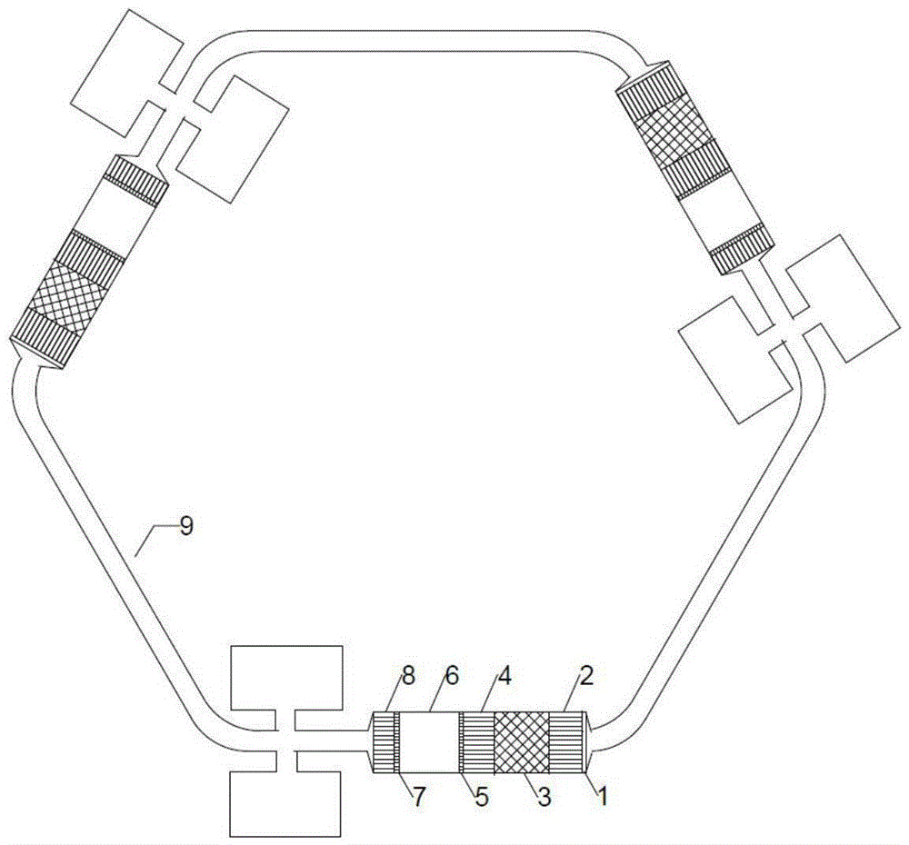
[0035] Figure 5 It is a structural schematic diagram of a multi-stage traveling wave thermoacoustic engine system (embodiment 2) for cascade utilization of high-temperature flue gas waste heat of the present invention. Such as Figure 5 As shown, the multi-stage traveling wave thermoacoustic engine system in this embodiment 2 is composed of 6 thermoacoustic engine units with the same structure and different sizes; the thermoacoustic engine units at all levels are connected end to end through resonance tubes 9 with different diameters Loop structure, each stage of thermoacoustic engine unit is in the traveling wave phase in the loop structure; each stage of thermoacoustic engine unit is connected in sequence by DC suppressor 1, main cooler 2, regenerator 3, heating 4, high temperature end layer fluidization element 5, thermal buffer pipe 6, room temperature end layer fluidization element 7 and secondary cooler 8;

[0036] Among them, the size of #1 to #6 thermoacoustic engin...


PUM


Abstract

The invention discloses a multi-stage traveling wave thermoacoustic engine system for cascaded utilization of waste heat of high temperature flue gas. The multi-stage traveling wave thermoacoustic engine system adopts a loop structure formed in such a way that N stages of thermoacoustic engine units are connected end to end through resonant tubes, wherein N is equal to a positive integer ranging from 3 to 10; the thermoacoustic engine units comprises direct current suppressors, primary coolers, regenerators, heaters, high-temperature end layer fluidifying elements, thermal buffer tubes, room-temperature end layer fluidifying elements, secondary coolers and the resonant tubes, which are connected in sequence; when the system works, the waste heat of high temperature flue gas passes through heaters of the thermoacoustic engine units in sequence, and is subjected to heat exchange with the heaters to enable the heater to generate high temperature, temperature gradient is formed at the regenerator of the engine, heat energy is converted into acoustic work under the temperature gradient, the acoustic work spreads in the positive direction of the temperature gradient, and is amplified for many times, and the system circularly works; no mechanical movement parts exist, the structure is simple, the waste heat of flue gas can be efficiently used in a cascade manner to generate acoustic work, and the energy conservation and emission reduction are achieved.

Description

technical field [0001] The invention belongs to the field of engines, and in particular relates to a multi-stage traveling wave thermoacoustic engine system for cascade utilization of high-temperature flue gas waste heat. Background technique [0002] Energy is an important basis for economic development and social progress, and energy conservation and emission reduction is a key issue for my country to better carry out modernization and develop a market economy. Waste heat utilization, as an important part of energy conservation and emission reduction, has great potential for development. Waste heat belongs to secondary energy. It is rich in resources in my country and widely exists in power plant boilers and industrial equipment. The total amount of high-temperature flue gas waste heat accounts for about 50% of the total waste heat resources. Boiler flue gas heat loss and automobile exhaust waste heat are the largest items of heat loss, not only wasting a lot of potential...

Claims


Application Information

Patent Timeline
Patent Type & Authority Applications(China)
IPC IPC(8): F03G7/00
CPCF03G7/00
Inventor 罗二仓徐静远张丽敏吴张华戴巍
Owner TECHNICAL INST OF PHYSICS & CHEMISTRY - CHINESE ACAD OF SCI
Why Eureka
Try Eureka