
High-speed permanent-magnet motor rotor with layered permanent magnet structure

A layered structure, permanent magnet motor technology, applied in the direction of magnetic circuit shape/style/structure, magnetic circuit rotating parts, etc., can solve the problem of excessive rotor opening, reduced rotor reliability, and excessive stress at the magnetic isolation bridge And other issues

Inactive Publication Date: 2015-08-26
SHENYANG INSTITUTE OF CHEMICAL TECHNOLOGY
View PDF7 Cites 3 Cited by
  • Summary
  • Abstract
  • Description
  • Claims
  • Application Information

AI Technical Summary

Problems solved by technology

[0004] The present invention provides a high-speed permanent magnet motor rotor with a layered permanent magnet structure. Reduce the reliability of the rotor and the local excessive stress at the magnetic isolation bridge, thereby reducing the problem of the operating life of the rotor, and at the same time reducing the problem of serious magnetic flux leakage of the built-in permanent magnet

Method used


Image

  • High-speed permanent-magnet motor rotor with layered permanent magnet structure

Examples


Embodiment Construction

[0013] The present invention will be described in detail below in conjunction with the accompanying drawings and specific embodiments.

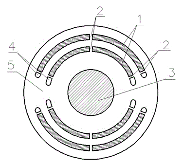
[0014] The invention provides a high-speed permanent magnet motor rotor, which includes a rotating shaft 3 , a rotor core 5 , a permanent magnet 1 , reinforcing ribs 2 , and a magnetic isolation bridge 4 . The layered permanent magnet 1 is nested in the rotor core 5. The rotor core 5 is made of laminated high-strength silicon steel sheets. The permanent magnet 1 is divided into multi-layer structures. The number of layers is greater than or equal to 2. Each layer of permanent magnet 1 is divided into multiple sections. , the number of segments is greater than or equal to 2, there is a non-magnetic reinforcing rib 2 between each permanent magnet 1, and there are reinforcing ribs 2 and magnetic isolation bridges 4 at both ends of each permanent magnet 1, and the outermost permanent magnet layer is a magnetic isolation bridge. 4 is small, and th...


PUM


Abstract

The invention relates to the motor rotor, particularly to a high-speed permanent-magnet motor rotor with a layered permanent magnet structure. The rotor is characterized in that the rotor comprises a rotating shaft (3), a rotor iron core (5), permanent magnets (1), reinforced ribs (2), and magnetic isolation bridges (4). The permanent magnets (1) are embedded into the rotor iron core (5) and are in a multi-layer mode, wherein the number of layers is larger than or equal to 2; each layer of permanent magnet (1) unit is divided into multiple segments, wherein the number of segments is larger than or equal to 2; and the reinforced ribs (2) are arranged among all permanent magnet segments. The reinforced ribs (2) and the magnetic isolation bridges (4) are arranged at the two ends of all layers of the permanent magnet (1); a smaller magnetic isolation bridge (4) is arranged at the permanent magnet layer approaching the outermost side of the rotor; and the magnetic isolation bridge (4) arranged at the inner layer of the permanent magnet are gradually increased. According to the invention, a problem that the rotor strenght is reduced due to too large magnetic isolation bridge arranged at the outer layer of the permanent magnet can be solved; and the leakage flux can be reduced with the dimensions of the magnetic isolation bridges at the inner layer of the permanent magnet.

Description

technical field [0001] The invention relates to a motor rotor, in particular to a high-speed built-in permanent magnet motor rotor, which has the characteristics of high reliability, low eddy current loss, small magnetic leakage coefficient and the like. Background technique [0002] Due to the high speed, high power density and small size, the high-speed motor can effectively save materials; due to the small moment of inertia, the dynamic response is fast; the high-speed motor can be directly connected with the working machine or load, eliminating the traditional mechanical transmission device , thus reducing noise and improving the efficiency of the transmission system. The research and application of high-speed motors meet the needs of economic development for energy saving and emission reduction. At present, it has become one of the research hotspots in the field of international electrical engineering. It has broad application prospects. [0003] Permanent magnet moto...

Claims


Application Information

Patent Timeline
IPC IPC(8): H02K1/27
Inventor 孔晓光
Owner SHENYANG INSTITUTE OF CHEMICAL TECHNOLOGY
Learn More