Self-driven transient stress sensing device
A sensing device, transient stress technology, applied in the direction of measuring device, measuring force, instrument, etc., can solve the problems of low current output density, there is no self-driven transient pressure sensing device, etc., to achieve reasonable design, improve Signal response strength, the effect of improving sensitivity
Active Publication Date: 2015-08-26
BEIJING INST OF NANOENERGY & NANOSYST
View PDF3 Cites 25 Cited by
- Summary
- Abstract
- Description
- Claims
- Application Information
AI Technical Summary
Problems solved by technology
However, due to the low current output density of contact triboelectric nanogenerators, a large area is generally required to effectively drive the monitoring equipment.
Therefore, so far, no self-driven transient pressure sensing device has been reported
Method used
View moreImage
Smart ImageViewing Examples
Examples
Embodiment 1
Login to View More PUM
| Property | Measurement | Unit |
|---|---|---|
| Thickness | aaaaa | aaaaa |
| Thickness | aaaaa | aaaaa |
Abstract
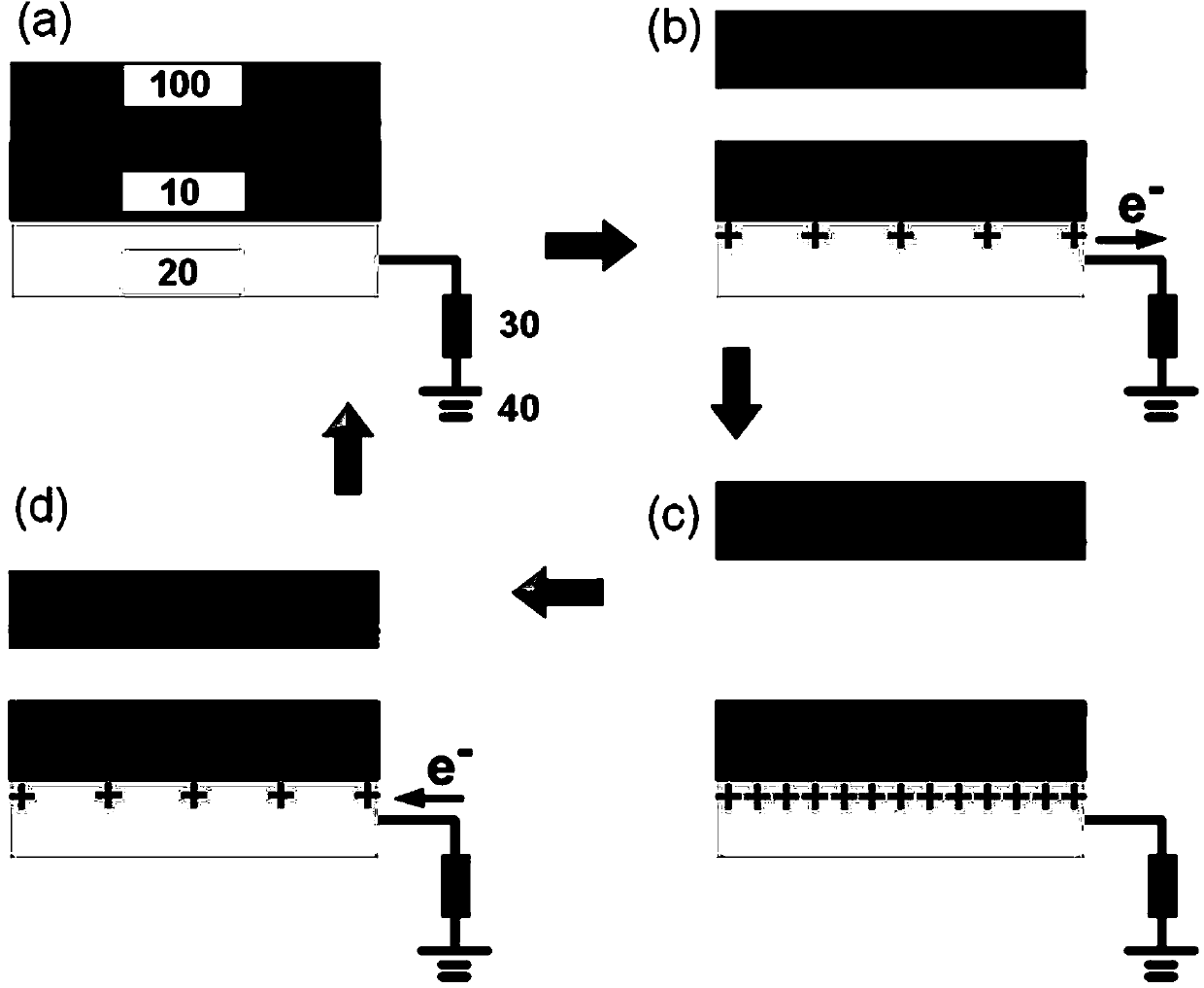
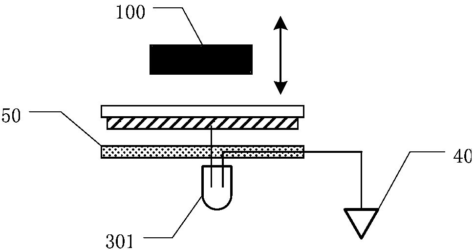
According to the present invention, by utilizing the characteristics of an electret material, an efficient contact-separation type friction nanometer generator is formed between a stress applying object and a sensing device contact layer, and is combined with the light emitting diodes skillfully, so that a self driven visual stress sensing device is constructed. Each light emitting diode corresponds to a friction nanometer generator unit, and when the external stress is applied to a contact layer of a sensor, a generated corresponding output signal drives the corresponding diode to emit light. The luminous intensity of the diodes is increased along with the increase of the applied stress, and the stress can be determined by analyzing the luminous intensity of the diodes, thereby realizing the visualization of the stress sensing. A stress visual device of the present invention has the characteristic of self-driven output, can analyze the external stress without needing an external power supply, and can be used to detect the spatial distribution of pressure.
Description
technical field The present invention relates to a stress sensing device, in particular to a self-driven transient stress sensing device. Background technique The existing transient stress sensing technology is mainly based on two kinds: (1) using field-effect transistors to modulate the channel resistance under different pressures to realize the sensing of external pressure; (2) using the piezoelectric photoelectron effect to The modulation of nanowire resistance is used to realize the sensing of external pressure. However, these two technologies all need an external power supply as the energy supply unit of the device, and if there is no power supply, they cannot work normally. This greatly limits the development and application of these pressure sensing technologies. The development of a transient pressure sensing technology that can work without an external power supply is the key to solving the above problems, and the successful development of triboelectric nanogene...
Claims
Login to View More Application Information
Patent Timeline
 IPC IPC(8): H02N1/04G01L1/00
Inventor 杨亚张虎林王中林
Owner BEIJING INST OF NANOENERGY & NANOSYST
Features
- R&D
- Intellectual Property
- Life Sciences
- Materials
- Tech Scout
- Unparalleled Data Quality
- Higher Quality Content
- 60% Fewer Hallucinations
Learn More Browse by: Latest US Patents, China's latest patents, Technical Efficacy Thesaurus, Application Domain, Technology Topic, Popular Technical Reports.
© 2025 PatSnap. All rights reserved.Legal|Privacy policy|Modern Slavery Act Transparency Statement|Sitemap|About US| Contact US: help@patsnap.com


