
An engine start-stop system based on double rotor motor and its working method

A dual-rotor motor and start-stop system technology is applied to the arrangement of multiple prime movers, power devices, and air pressure power devices of a general power device. It can solve the problems of complex systems, scattered components, and failure to integrate, and achieve The effect of small size, compact structure and light weight

Active Publication Date: 2017-09-05
武汉投知家信息科技有限公司
View PDF5 Cites 0 Cited by
  • Summary
  • Abstract
  • Description
  • Claims
  • Application Information

AI Technical Summary

Problems solved by technology

The above ideas and methods have their own characteristics and advantages, but they all have problems such as complex systems and scattered components, which cannot be effectively integrated with the hybrid system of medium and severe hybrid vehicles.

Method used


Image

  • An engine start-stop system based on double rotor motor and its working method
  • An engine start-stop system based on double rotor motor and its working method
  • An engine start-stop system based on double rotor motor and its working method

Examples


Embodiment 1

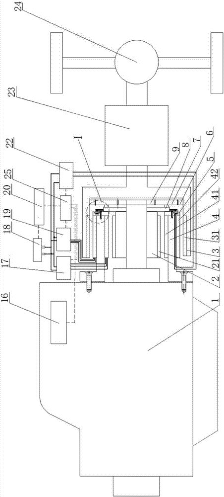
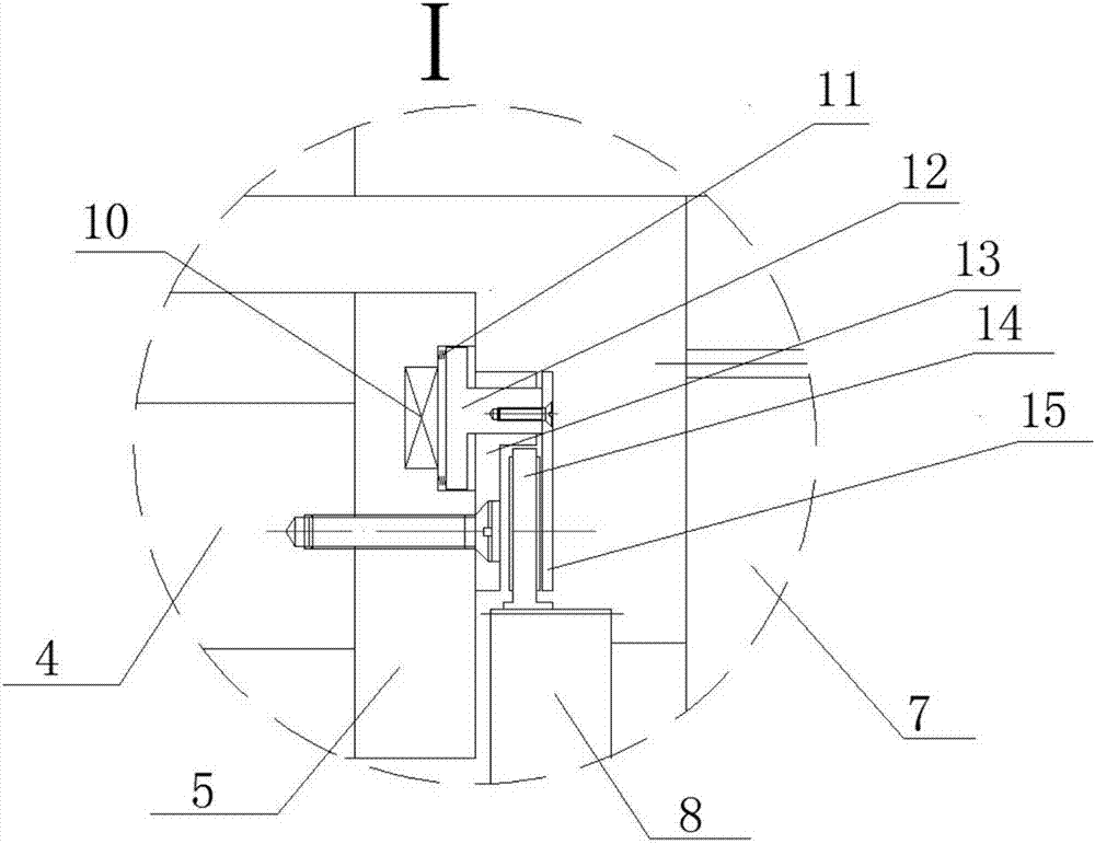
[0037] Such as figure 1 As shown, an engine start-stop system of the present invention mainly includes an engine 1, a double-rotor motor, a planetary gear mechanism, an electromagnetic clutch, a composite power supply, and a drive control system.

[0038] The dual-rotor motor includes an inner rotor 2 , an outer rotor 3 and a stator 4 in the middle. The rotating shaft of the inner rotor 2 is connected with the output shaft of the engine and rotates synchronously. Simultaneously, the sun gear 9 of the planetary gear mechanism is also contained on the rotating shaft of the inner rotor 2, and the two also rotate synchronously. The rotating shaft of the outer rotor 3 is connected with the gearbox input shaft and rotates synchronously. The outer rotor 3 is embedded with a ring gear 6, and the ring gear 6 and the outer rotor 3 also rotate synchronously.

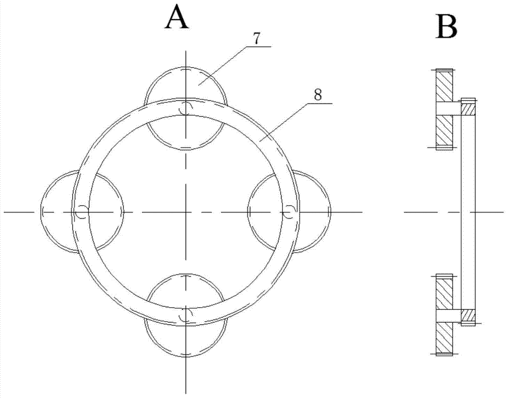
[0039] The stator 4 of the dual-rotor motor is in the shape of a barrel with a skirt, and the skirt has bolt holes, which are c...

Embodiment 2

[0055] On the basis of Embodiment 1, the present invention also provides a working method of an engine start-stop system based on a dual-rotor motor.

[0056] This working method includes:

[0057] (1) The engine starts. When the power of the composite power supply is sufficient, the speed requirement of the vehicle is not high, and the outer motor of the dual-rotor motor can meet the power demand of the vehicle, the outer motor of the dual-rotor motor drives the vehicle. Neither its engine worked. When the power of the composite power supply drops to the point that it cannot meet the power supply demand of the external motor of the dual-rotor motor, the power supply detection circuit detects the signal that the power storage of the composite power supply is insufficient, and transmits the signal to the control unit, and the control unit sends a drive to the internal motor drive circuit Signal, the internal motor works, and the internal motor drives the engine to rotate at a...


PUM


Abstract

The invention discloses an engine start-stop system based on a double-rotor motor and a working method thereof, including an engine, a double-rotor motor, a planetary gear mechanism, an electromagnetic clutch, a composite power supply and a drive control system; the inner rotor shaft of the double-rotor motor and the engine output Shaft connection, also connected with the sun gear of the planetary gear mechanism, the outer rotor shaft of the dual-rotor motor is connected with the input shaft of the gearbox, the outer rotor is embedded with a ring gear, and the planetary gear carrier can be fixed without rotation through the electromagnetic clutch; the drive control system Including composite power supply, internal motor drive circuit, external motor drive circuit, power supply power detection circuit, electromagnetic clutch drive circuit and control unit; through the control of the double-rotor motor and the cooperation of the engine control unit, the engine can be started conveniently with downtime. The invention has compact structure and has the basic function of hybrid power.

Description

technical field [0001] The invention belongs to the field of engines, and in particular relates to an engine start-stop system based on a double-rotor motor and a working method thereof. Background technique [0002] At present, in order to reduce the fuel consumption of automobile engines and reduce air pollution, people have invented many new technologies, such as gasoline engine direct injection technology, crankcase ventilation system, hybrid drive technology and the engine start-stop system involved in the present invention etc. The engine start-stop system starts or stops the engine according to the vehicle's operating conditions, which can effectively reduce the engine idling time, or reduce the engine's low-efficiency working time, thereby improving the fuel economy of the vehicle. The engine start-stop system is an essential system for current hybrid vehicles and extended-range electric vehicles, and it is also an effective means for conventional fuel engine vehicl...

Claims


Application Information

Patent Timeline
Patent Type & Authority Patents(China)
IPC IPC(8): B60K6/26B60K6/36
Inventor 何仁蒋科军
Owner 武汉投知家信息科技有限公司
Learn More