Roller control system of rotor spinning machine

A technology of rotor spinning machine and control system, applied in spinning machine, open-end spinning machine, continuous winding spinning machine, etc., can solve problems affecting yarn quality, operation efficiency, etc., and reduce deviations opportunities, the effect of improving yarn quality

Inactive Publication Date: 2015-09-02
ZHEJIANG RIFA TEXTILE MASCH CO LTD
View PDF8 Cites 3 Cited by
  • Summary
  • Abstract
  • Description
  • Claims
  • Application Information

AI Technical Summary

Problems solved by technology

[0003] The purpose of the present invention is to overcome the defect that the existing rotor spinning machine cannot timely feedback the speed of the stepping motor and the roller, which affects the quality of the yarn and the operating efficiency of the machine, and provides an opportunity to reduce the deviation of the speed of the spindle roller. Roller Control System of Rotor Spinning Machine for Improving Operational Efficiency of Rotor Spinning Machine

Method used


Image

  • Roller control system of rotor spinning machine
  • Roller control system of rotor spinning machine
  • Roller control system of rotor spinning machine

Examples


Embodiment approach 1

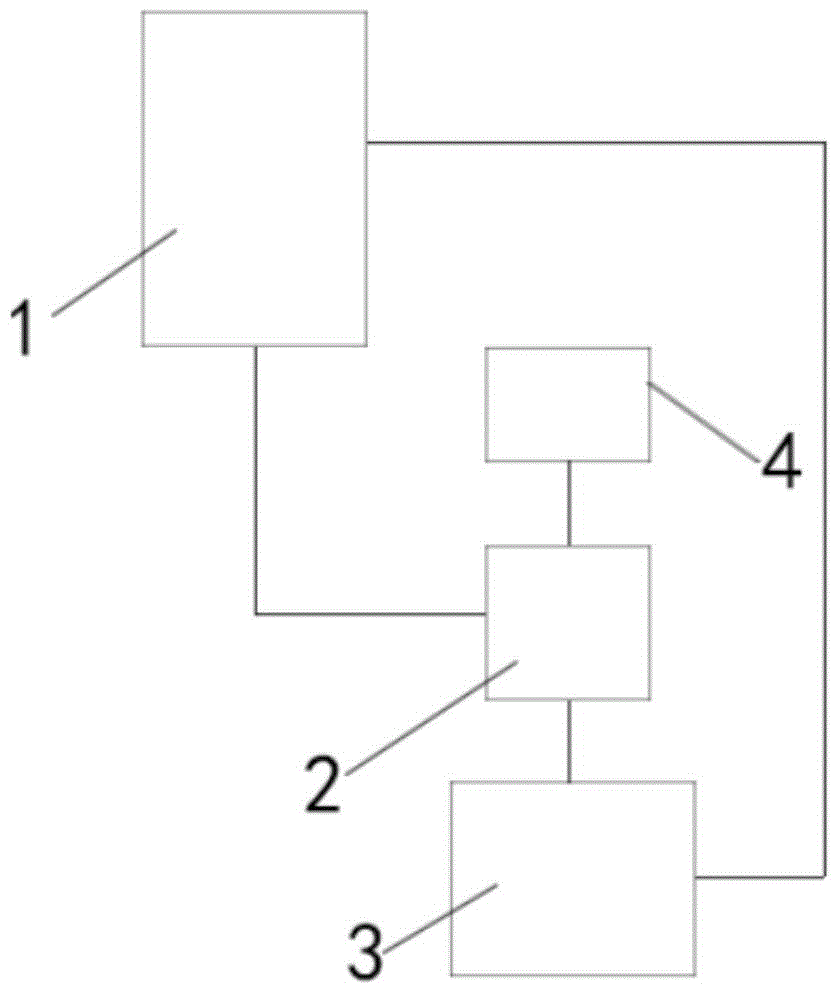
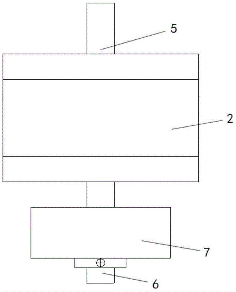
[0017] Embodiment 1, such as figure 1 Shown, the present invention comprises controller 1 and stepping motor 2, and stepping motor 2 drives roller to rotate, and controller 1 controls the work of stepping motor 2, and the front end of motor shaft 5 of described stepping motor 2 and roller shaft The transmission connection drives the roller shaft to rotate. The rear end of the motor shaft extends axially from the housing of the stepper motor 2 to form an extension shaft 6. A speed measuring device 3 is installed on the extension shaft. The speed measuring device 3 is an encoder 7. Device 7 is installed on described extension shaft 6, and encoder 7 carries out real-time monitoring to the rotating speed of motor shaft 5 of stepper motor 2, and encoder 7 carries out signal connection with described controller 1, and described controller 1 The control program of the control program is provided with a speed comparison module and a speed adjustment module. The speed measuring device ...

Embodiment approach 2

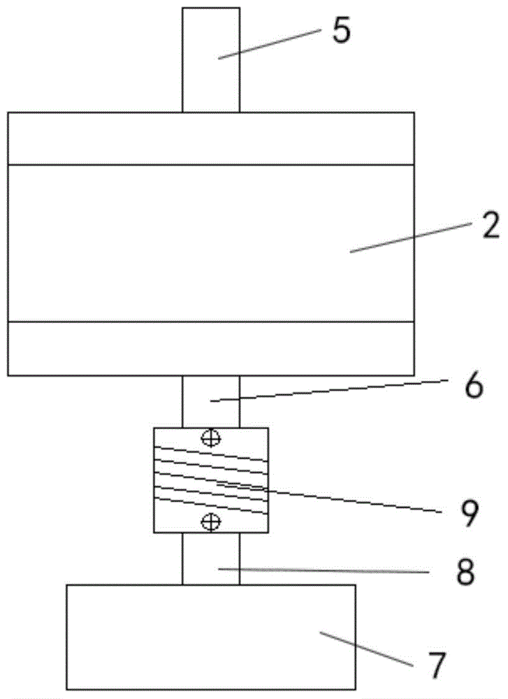
[0018] Implementation mode two, such as image 3 As shown, the encoder described in the above embodiment is installed on a rotating shaft 8 , and the rotating shaft 8 is connected with the extension shaft 6 of the motor through a coupling 9 .

Embodiment approach 3

[0019] Implementation mode three, such as Figure 4 As shown, the speed measuring device 3 described in the first embodiment above can also be composed of a code disc 10 and an induction switch, the code disc 10 is fixedly set on the extension shaft 6 of the motor shaft 5, and the induction switch is a photoelectric switch 11 , The photoelectric switch 11 is fixedly installed with the outer ring part of the code disc 10, which improves the speed detection accuracy.


PUM


Abstract

The invention relates to a roller control system of a rotor spinning machine and belongs to the technical field of textile machinery. The roller control system comprises a controller and a stepping motor. The stepping motor drives a roller to rotate. The controller controls the stepping motor to operate. The front end of the shaft of the stepping motor is in transmission connection with a roller shaft and drives the roller shaft to rotate. The rear end of the shaft of the stepping motor axially extends out of the shell of the stepping motor to form an extension shaft. A speed measuring device is mounted on the extension shaft. The speed measuring device is in signal connection with the controller. The control program of the controller is provided with a speed comparison module and a speed regulating module. By the roller control system, the problem that yarn quality and machine operation efficiency are affected due to the fact that the rotation speed of the stepping motor and the roller of an existing rotor spinning machine cannot be fed back timely is solved, spindle position roller speed deviation change is reduced, and rotor spinning machine operation efficiency is increased.

Description

technical field [0001] The invention belongs to the technical field of textile machinery, and in particular relates to a roller control system of a rotor spinning machine. Background technique [0002] In the rotor spinning machine, the fed fiber slivers are opened into single fibers by the rotary carding roller covered with card clothing, and are transported to the inner wall of the high-speed rotating rotor along with the airflow, and the yarn tail is formed in the condensation groove. The twisted yarn is drawn out and directly wound into a bobbin. Most of the rollers of the current rotor spinning machine are driven by stepping motors. The driving mode of ordinary stepping motors belongs to open-loop control. The controller does not know the current speed and position of the stepping motor. If the stepping motor appears Problems, such as out-of-step, stalled, etc., the controller cannot obtain the current running speed of the stepping motor and the roller in time, which...

Claims


Application Information

Patent Timeline
Patent Type & Authority Applications(China)
IPC IPC(8): D01H4/08D01H4/38D01H4/44
Inventor 戴小平
Owner ZHEJIANG RIFA TEXTILE MASCH CO LTD
Why Eureka
Try Eureka