Prefabricated shear wall horizontal abutted seam buckle welding built-up connection device

A technology of horizontal jointing and combined connection, applied in the direction of walls, building components, buildings, etc., can solve the problems of high welding cost, high difficulty, hindering the installation of horizontally distributed steel bars, etc. The effect of assembling time-saving and labor-saving

Inactive Publication Date: 2015-09-02
ARCHITECTURAL DESIGN & RES INST OF SOUTH CHINA UNIV OF TECH
View PDF5 Cites 18 Cited by
  • Summary
  • Abstract
  • Description
  • Claims
  • Application Information

AI Technical Summary

Problems solved by technology

According to the existing technology of using the sleeve grouting connection device, the number of sleeves is the same as the number of vertical steel bars in the upper prefabricated shear wall 1 and the lower prefabricated shear wall 4, which requires a lot of sleeves, and the material cost is very high. Moreover, each sleeve needs to be embedded in an accurate position, and grout needs to be filled into the sleeve, which is difficult and time-consuming
[0021] 2. According to the existing technology using the slurry anchor connection device, the number of spiral hoops is the same as the number of vertical steel bars in the upper prefabricated shear wall 1 and the lower prefabricated shear wall 4, which requires a lot of spiral hoops, and the material cost is very high , and each spiral hoop needs to be embedded in an accurate position, and needs to be grouted into the sleeve, which is difficult and time-consuming
[0022] 3. According to the existing technology of adopting the pre-welded steel plate and the steel bar welding connection device, the upper connecting steel bar 3 and the connecting steel plate 8 need to be overlapped and welded, and then the lower connecting steel bar 5 and the connecting steel plate 8 should be overlapped and welded. There are many, so the welding cost is very high, and it is time-consuming
[0023] 4. According to the existing technology of adopting the lap joint welding connection device of steel bars, the upper connecting steel bars 3 and the lower connecting steel bars 5 need to be welded one by one by lap joints. Due to the large number of steel bars, the welding cost is very high and labor-consuming
The bottom of the upper prefabricated shear wall 1 also has such horizontally distributed steel bars. According to the existing technology of using pre-welded steel plate and steel bar welding connection device and adopting the overlapping welding connection device of steel bars, there are concave holes at the bottom of the upper prefabricated shear wall 1. grooves, which caused inconvenience in the manufacture of the upper prefabricated shear wall 1, and also hindered the setting of horizontally distributed steel bars in the upper prefabricated shear wall 1
[0026] 7. In order to ensure the quality of grouting and compact connection, a gap of 20 mm is set between the upper prefabricated shear wall 1 and the lower prefabricated shear wall 4 in the prior art, so that before the post-grouting material reaches a certain strength, it must be installed Enough and reliable brackets can make the upper prefabricated shear wall 1 positioned and stable, which consumes materials and man-hours
However, this will easily cause dislocation of the upper prefabricated shear wall 1 and the lower prefabricated shear wall 4 when the upper prefabricated shear wall 1 is hoisted, making it difficult to align

Method used


Image

  • Prefabricated shear wall horizontal abutted seam buckle welding built-up connection device
  • Prefabricated shear wall horizontal abutted seam buckle welding built-up connection device
  • Prefabricated shear wall horizontal abutted seam buckle welding built-up connection device

Examples


Embodiment Construction

[0061] In order to further understand the present invention, the present invention will be further described below in conjunction with the accompanying drawings, but the protection scope of the present invention is not limited to the scope expressed in the embodiments.

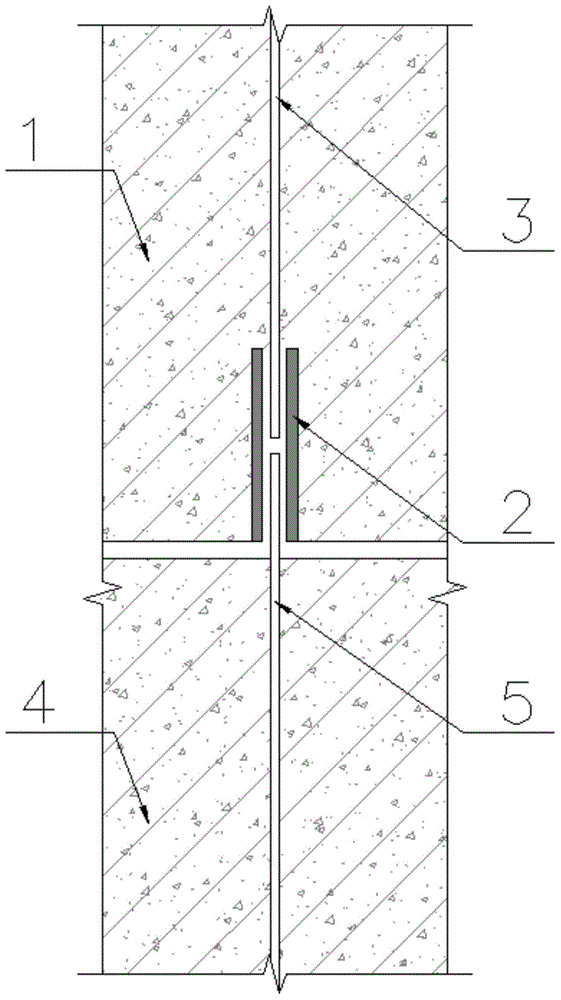
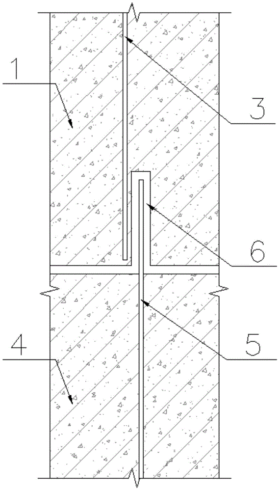
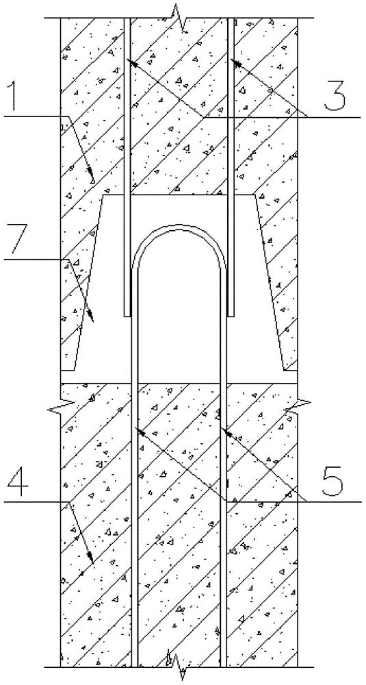
[0062] Such as Figure 5 As shown, an assembled shear wall horizontal seam buckle welding combined connection device is used for the connection of the horizontal seam when assembling the upper prefabricated shear wall 1 and the lower prefabricated shear wall 4. It mainly consists of the upper anchor plate 9, The last connection reinforcement 3, the upper horizontal reinforcement 15, the vertical connection bolt 10, the lower anchor plate 11, the lower connection reinforcement 5, the lower horizontal reinforcement 16, the connection groove box 12, the compression spring 13, the connection block 14 and the hinge 17 form.

[0063] The upper anchor plate 9 is set close to the bottom surface of the upper prefabrica...


PUM


Abstract

The invention discloses a prefabricated shear wall horizontal abutted seam buckle welding built-up connection device. An upper anchor plate clings to the bottom surface of an upper prefabricated shear wall, and the top of the upper anchor plate is provided with upper horizontal reinforced bars and connected with bottom ends of upper connecting reinforced bars; the upper connecting reinforced bars are arranged in the upper prefabricated shear wall; the upper portion of a vertical connecting plug pin is located in the upper prefabricated shear wall and connected with the upper connecting reinforced bars, the lower portion of the vertical connecting plug pin protrudes out of the bottom surface of the upper prefabricated shear wall, and the bottom end of the same is an expanded head; a lower anchor plate clings to the top face of a lower prefabricated shear wall and connected with the top ends of lower connecting reinforced bars; connecting blocks are arranged inside a connecting groove box in pairs, opposite protruding snag teeth are arranged at the top ends of the connecting blocks, and the bottom ends of the connecting blocks are connected with the bottom of the connecting groove box through hinges; pressure springs are arranged between the connecting blocks and the inner wall of the connecting groove box. The connecting device can bear shear force, bending moment and tension and pressure, the prefabricated shear wall assembly process is simplified, construction period is shortened, labor cost is reduced, and on-site pollution and material waste are reduced.

Description

technical field [0001] The invention relates to an assembly-type shear wall horizontal joint buckle welding combined connection device, which is used for connecting the horizontal joints when assembling an upper prefabricated shear wall and a lower prefabricated shear wall, and belongs to the field of construction engineering. Background technique [0002] Shear wall is a very widely used component type in construction engineering, which is used to bear vertical loads (such as the self-weight of buildings, service loads, etc.) and horizontal actions (such as wind, horizontal earthquakes, etc.). In general, a shear wall bears shear, bending moment, compression and tension. [0003] There are generally two ways to construct shear walls: "cast-in-place" and "assembly". "Cast-in-place" is a traditional construction method: tie steel bars on the construction site, set up formwork and supports, pour concrete into the formwork and vibrate compactly, and the formwork can be removed...

Claims


Application Information

Patent Timeline
Patent Type & Authority Applications(China)
IPC IPC(8): E04B2/56E04B1/41
Inventor 韦宏王帆许晓峰黄昌辉
Owner ARCHITECTURAL DESIGN & RES INST OF SOUTH CHINA UNIV OF TECH
Why Eureka
Try Eureka