

Automatic-control constant-pressure throttling valve
A technology of throttle valve and inlet pressure, applied in valve details, safety valve, balance valve, etc., can solve the problems of automatic take-off and excessive pressure change of safety valve.
- Summary
- Abstract
- Description
- Claims
- Application Information
AI Technical Summary
Problems solved by technology
Method used
Image

Examples
Embodiment 1
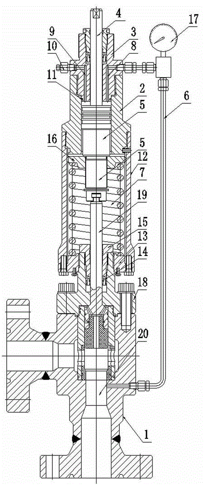
[0027] A self-controlled constant pressure throttle valve, including a valve body 1 and an actuator, the actuator includes a cylinder 2, a cylinder head 3, a piston 5, a pressure taking tube 6 and an elastic element, and the cylinder 2 is fixed on the valve Above the main body 1, the cylinder head 3 is fixed on the upper part of the cylinder body 2, the piston 5 is movably arranged in the cylinder body 2, and the lower part of the piston 5 is fixed on the valve stem 19 of the valve main body 1, and the elastic element is fixedly arranged Between the cylinder body 2 and the valve main body 1, and the elastic element is fixedly connected with the piston 5; Set above the piston 5 in the cylinder body 2; when the pressure at the output end 20 of the valve main body 1 increases, the medium pressure is transmitted to the top of the piston 5 through the pressure sensing tube 6 to make the piston 5 move down, and the piston 5 indirectly drives the valve stem 19 and the valve. The flap...
Embodiment 2
[0035]A self-controlled constant pressure throttle valve, including a valve body 1 and an actuator, the actuator includes a cylinder 2, a cylinder head 3, a piston 5, a pressure taking tube 6 and an elastic element, and the cylinder 2 is fixed on the valve Above the main body 1, the cylinder head 3 is fixed on the upper part of the cylinder body 2, the piston 5 is movably arranged in the cylinder body 2, and the lower part of the piston 5 is fixed on the valve stem 19 of the valve main body 1, and the elastic element is fixedly arranged Between the cylinder body 2 and the valve main body 1, and the elastic element is fixedly connected with the piston 5; Set above the piston 5 in the cylinder body 2; when the pressure at the output end 20 of the valve main body 1 increases, the medium pressure is transmitted to the top of the piston 5 through the pressure sensing tube 6 to make the piston 5 move down, and the piston 5 indirectly drives the valve stem 19 and the valve. The flap ...
PUM
 Abstract
Description
Claims
Application Information