
Optical fiber coupling module

A fiber coupling and coupling module technology, applied in the coupling of optical waveguides and other directions, can solve the problems of unusable devices, unreplaceable fibers, scrapped or repaired lasers, etc., and achieves the effect of improving simplicity and facilitating replacement and maintenance.

Inactive Publication Date: 2015-09-02
INNOLIGHT TECHNOLOGY (SUZHOU) LTD
View PDF5 Cites 0 Cited by
  • Summary
  • Abstract
  • Description
  • Claims
  • Application Information

AI Technical Summary

Problems solved by technology

In practical application, the optical fiber coupling method mainly fixes the output optical fiber and the optical fiber socket of the optical module by welding, and the optical fiber cannot be replaced. If the optical fiber is damaged, the entire laser can only be scrapped or repaired

Method used


Image

  • Optical fiber coupling module
  • Optical fiber coupling module
  • Optical fiber coupling module

Examples


Embodiment Construction

[0020] The application will be described in detail below in conjunction with specific implementations shown in the accompanying drawings. However, these implementations do not limit the present application, and any structural, method, or functional changes made by those skilled in the art based on these implementations are included in the protection scope of the present application.

[0021] In each drawing of the present application, some dimensions of structures or parts are exaggerated relative to other structures or parts for convenience of illustration, and therefore, are only used to illustrate the basic structure of the subject matter of the present application.

[0022] In addition, terms used herein such as "upper", "above", "under", "below", etc. to express relative positions in space are for convenience of description to describe a unit or feature as shown in the drawings relative to A relationship to another cell or feature. The terms of spatial relative position ...


PUM


Abstract

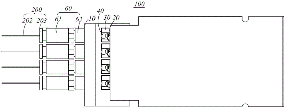
The invention discloses an optical fiber coupling module, which comprises a shell and optical assembles, wherein the shell is provided with optical channels. The optical fiber coupling module is characterized in that a lens is located at a light propagation path of the optical assembly; a hollow socket assembly is connected at the optical channel in a ring manner; a limiting member is located inside the socket assembly, and the limiting member is provided with a through hole which is mutually communicated with the optical channel; and the limiting member comprises a contact surface which prevents an optical fiber jumper from moving, when an external optical fiber jumper is inserted into a cavity of the socket assembly, the end face of the optical fiber jumper is contacted with the contact surface of the limiting member, and light is coupled to the optical fiber jumper through the lens, the optical channel and the through hole. According to the technical scheme disclosed by the invention, the socket assembly is internally provided with the limiting member with the contact surface which has excellent coupling efficiency, the external optical fiber jumper is enabled to acquire excellent light coupling efficiency by being inserted into the bottom part of the socket assembly and arriving at the contact surface, the convenience in light coupling efficiency adjustment is improved, and replacement and maintenance of the optical fiber jumper are facilitated.

Description

technical field [0001] The invention belongs to the technical field of manufacturing optical communication components, and in particular relates to an optical fiber coupling module. Background technique [0002] In existing laser displays or other occasions that require high-power laser output, semiconductor lasers are usually used as light sources. The output power of a single semiconductor laser or semiconductor laser packaging module is low, which often cannot meet the requirements of laser display for high-power laser light sources. In practical applications, it is often necessary to shape and combine the output lights of multiple independent semiconductor lasers together for output. [0003] At present, there are two ways to combine the output light of multiple semiconductor lasers, the micro-optical system coupling method and the fiber array coupling method. In practical application, the optical fiber coupling method mainly fixes the output optical fiber and the optic...

Claims


Application Information

Patent Timeline
IPC IPC(8): G02B6/32
CPCG02B6/32
Inventor 孙雨舟于登群张永干常江
Owner INNOLIGHT TECHNOLOGY (SUZHOU) LTD
Learn More