
Engine equipped with turbocharger

一种涡轮增压器、发动机的技术,应用在机器/发动机、发动机点火、发动机元件等方向,能够解决耗油性能恶化、泵浦损失增大等问题,达到改善耗油性能的效果

Inactive Publication Date: 2015-09-02
MAZDA MOTOR CORP
View PDF8 Cites 14 Cited by
  • Summary
  • Abstract
  • Description
  • Claims
  • Application Information

AI Technical Summary

Problems solved by technology

This will lead to increased pumping losses, which will worsen fuel consumption

Method used


Image

  • Engine equipped with turbocharger
  • Engine equipped with turbocharger
  • Engine equipped with turbocharger

Examples


Embodiment Construction

[0023] (1) The overall structure of the engine

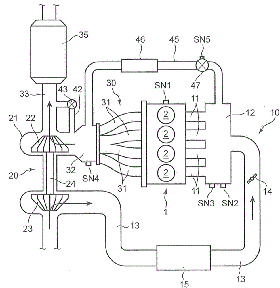
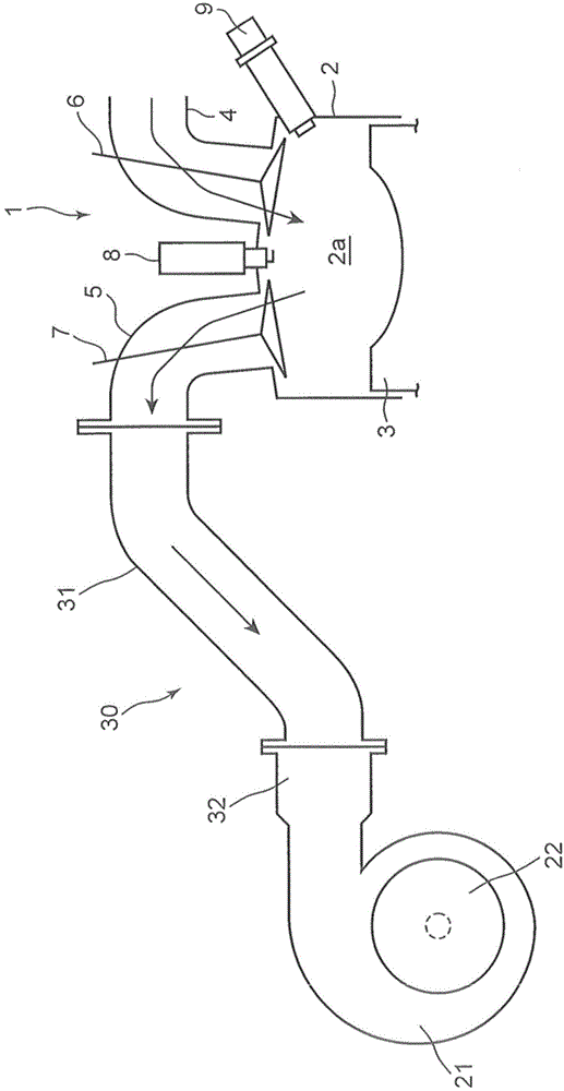
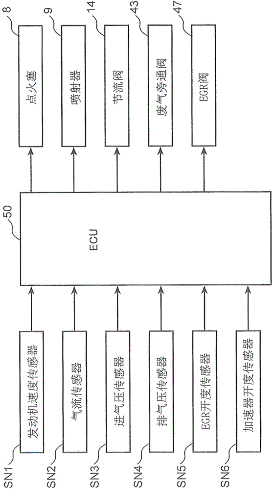
[0024] figure 1 and figure 2 An engine with a turbocharger according to an embodiment of the present invention is shown. The engine shown in this figure is a four-stroke spark ignition multi-cylinder gasoline engine mounted on a vehicle as a power source for running. Specifically, the engine of the present embodiment includes: a tandem four-cylinder engine main body 1 having four cylinders 2 arranged in a row; an intake passage 10 for introducing air into each cylinder 2 of the engine main body 1; An exhaust passage 30 for discharging exhaust gas generated in each cylinder 2 of the engine body 1; and a turbocharger 20 driven by energy of the exhaust gas.

[0025] Pistons 3 are respectively inserted into the respective cylinders 2 of the engine main body 1 . These pistons 3 are reciprocally slidable, and a combustion chamber 2 a is defined above the respective pistons 3 . In the combustion chamber 2a, a mixture of fuel and a...


PUM


Abstract

An engine includes: a turbocharger including a turbine and a compressor; an EGR passage connecting an exhaust passage on an upstream side of the turbine and an air intake passage on a downstream side of the compressor; an EGR valve provided in the EGR passage; a bypass passage that bypasses the turbine; and a waste gate valve provided in the bypass passage. In the engine, when a boost pressure is increased to a limit pressure, a first boost pressure control is executed, in which the EGR valve is opened and the waste gate valve is closed. After the first boost pressure control starts, when an engine speed is increased to a prescribed value, a second boost pressure control is executed, in which the waste gate valve is opened in addition to the EGR valve.

Description

technical field [0001] The present invention relates to an engine with a turbocharger provided with a turbocharger comprising a turbine driven by the energy of exhaust gas passing through an exhaust passage, air pressurized compressor. Background technique [0002] A turbocharger realizes high engine output by using the energy of exhaust gas discharged from the engine, and has been widely used in various engines from the past. [0003] In an engine employing the above-mentioned turbocharger, the supercharging pressure reaches the limit pressure when the rotational speed of the engine rises to a certain level, and then it is necessary to perform supercharging pressure control so that the supercharging pressure does not exceed the limit pressure. [0004] For example, an engine with a turbocharger shown in Patent Document 1 below has a bypass passage for bypassing the turbine of the turbocharger and a wastegate valve provided in the bypass passage. When the engine speed reach...

Claims


Application Information

Patent Timeline
Patent Type & Authority Applications(China)
IPC IPC(8): F02D23/00F02B31/00F02B37/00F02D21/08F02D23/02F02D41/02F02D41/34F02D43/00F02D45/00F02M25/07F02P3/01
CPCF02B37/00F02M25/0715F02B37/183F02D23/02F02D21/08Y02T10/44F02D23/00F02D41/005Y02T10/47Y02T10/144F02D37/02F02M25/07F02D41/402F02B31/00F02D41/0007F02M25/0706F02M25/0707F02M25/0726F02P15/02F02B17/005F02B23/104F02B29/0406F02B2023/085F02B2023/108F02M26/20F02M26/05F02M26/13F02M26/23Y02T10/12Y02T10/40F02B31/02
Inventor 山形直之辻田周平
Owner MAZDA MOTOR CORP
Learn More