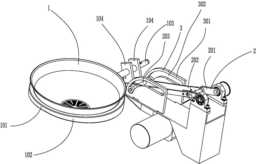
Automatic wok tossing system with fixed guide rail
A fixed and automatic technology, applied to cooking utensils, household appliances, applications, etc., can solve the problems of small range of activities, large installation space, and large equipment volume, so as to avoid heat waste and fuel waste, reduce equipment volume, The effect of the small size of the device
- Summary
- Abstract
- Description
- Claims
- Application Information
AI Technical Summary
Problems solved by technology
Method used
Image
Examples
Embodiment 1
[0056] like figure 1 As shown, the automatic pot-turning system of this embodiment includes a drag-pan type pot moving device; the drag-pan type pot moving device includes a pot 1, a pot driving device 2, and a curved guide rail 3; wherein,
[0057] The curved guide rail 3 includes two identical guide groove blocks 301 arranged in parallel in pairs, and each guide groove block 301 is provided with a guide groove 302; the guide groove 302 includes a horizontal section and an arc that is connected with the horizontal section and opens downward. line segment.
[0058] The pot driving device 2 includes a crank 201 , a connecting rod 202 , and a sliding column 203 . Both the connecting rod 202 and the guide groove 302 are arranged in parallel in pairs. One end of the connecting rod 202 is a crank end, which is hinged with the crank 201 ; the other end is a pot end, which is fixedly connected with the pot 1 . The sliding column 203 is located between the crank end of the connecti...
Embodiment 2
[0061] The difference between this embodiment and Embodiment 1 is that it further includes a pushing tool and its driving device, wherein the pushing tool is in the shape of a frying spoon. Its driving device is a crank rocker mechanism, which includes a crank driven to rotate by a power device, a rocker, and a connecting rod between the two; the frying spoon includes a handle, and the end of the handle is connected to the connecting rod. Wherein the crank of the crank rocker mechanism is driven by a motor and a reducer through a belt.
Embodiment 3
[0063] The difference between this embodiment and Embodiment 2 is that: the driving device of the pushing tool includes a first runner, a second runner, a first connecting rod, and a second connecting rod, and the first runner is a driving wheel; The top ends of the connecting rod and the second connecting rod are hinged with a slider, and the slider moves in a guide groove; the bottom end of the first connecting rod is connected to a non-central point on the first runner; the bottom end of the second connecting rod The end is connected to a non-central point on the second rotating wheel; the pushing tool is in the shape of a frying spoon, which includes a spoon handle, and the end of the spoon handle is connected to a non-central point on the second rotating wheel.
PUM
 Abstract
Description
Claims
Application Information
 - Generate Ideas
- Intellectual Property
- Life Sciences
- Materials
- Tech Scout
- Unparalleled Data Quality
- Higher Quality Content
- 60% Fewer Hallucinations
Browse by: Latest US Patents, China's latest patents, Technical Efficacy Thesaurus, Application Domain, Technology Topic, Popular Technical Reports.
© 2025 PatSnap. All rights reserved.Legal|Privacy policy|Modern Slavery Act Transparency Statement|Sitemap|About US| Contact US: help@patsnap.com

