Vertical mold for pouring and cooling ferroalloys

A ferroalloy and mold technology, applied in the field of vertical molds, can solve the problems of inability to meet the large-scale requirements of ferroalloy furnaces, mold demolding and breaking trouble, mold surface damage, etc., to achieve the effect of less powder, less labor requirements, and less segregation

Active Publication Date: 2017-10-10
吴绍相
View PDF5 Cites 0 Cited by
  • Summary
  • Abstract
  • Description
  • Claims
  • Application Information

AI Technical Summary

Problems solved by technology

[0002] Most of the existing molds adopt the horizontal mode, which occupies a large area, and most of the existing molds use preset cooling devices (water cooling, that is, embedded water cooling pipes) in the side wall or bottom plate of the mold. , it is prone to damage on the inner surface of the mold, resulting in the contact of the molten metal liquid with water, resulting in a hydrogenation reaction, and then an explosion, resulting in a safety accident. In addition, the demoulding and crushing of the mold are more troublesome. Taking crushing as an example, due to the traditional Mechanically crushed products have a lot of powder, which reduces the recovery rate. Therefore, when crushing, manual crushing is generally used instead of mechanical crushing, which makes the production cost of the final product higher and the automation effect is poor, which cannot meet the large-scale requirements of ferroalloy furnaces.

Method used


Image

  • Vertical mold for pouring and cooling ferroalloys
  • Vertical mold for pouring and cooling ferroalloys
  • Vertical mold for pouring and cooling ferroalloys

Examples


Embodiment Construction

[0025] The present invention is described in detail below in conjunction with accompanying drawing description:

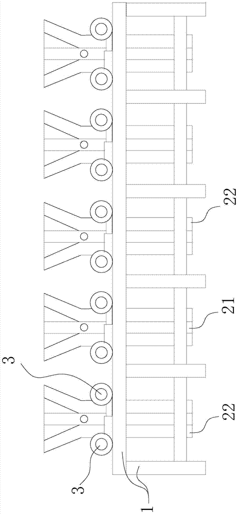
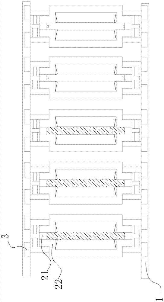
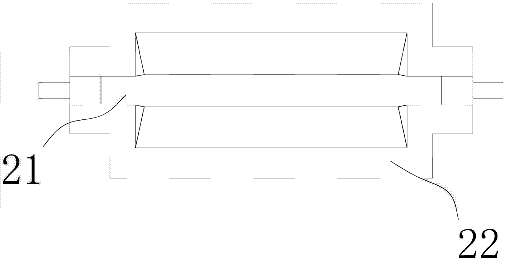
[0026] Such as Figure 1-9 Shown: it includes support frame 1, mold, opening and closing device 3, cooling device,

[0027] Described mold comprises support formwork 21 and side plate 22, and described support formwork is that front side, bottom, rear side are provided with baffle plate, and the mold that front side, bottom, rear side baffle plate are connected successively, in support formwork The front and rear side walls or / and the inner side walls of the bottom plate are provided with limiting projections 23. There are two side plates, which are respectively located on the left and right sides of the back form, and can be separated or merged with the back form, and when the side plates When combined with the support form, the support form 21 and the side plate 22 can form a container with an opening only on the top and a cavity in the middle;

[0028] The sup...


PUM


Abstract

The invention relates to a vertical mold for iron alloy pouring and cooling. It includes a support frame, a mould, an opening and closing device, and a cooling device. The mold includes a backing mold and side plates. Limiting protrusions are provided on the front and rear side walls or / and the inner side wall of the bottom plate. There are two side plates, which are located on the left and right sides of the support form, and can be separated or combined with the support form. When the side plates When combined with the support form, the support form and the side plates can form a container with an opening only on the top and a cavity in the middle. The support form is set on the support frame, and the side plates are connected to the support frame through the opening and closing device , and the opening and closing device controls the opening and closing of the side panels. It has the advantages of small footprint, labor saving, high automation level, high safety factor, fast cooling speed, high quality of finished products, and the product is not easy to segregate.

Description

technical field [0001] The invention relates to the field of moulds, in particular to a vertical ferroalloy pouring cooling machine which is small in floor area, easy to demould, broken, and fast in cooling, suitable for metal silicon, ferrosilicon, ferrochrome, silicomanganese, ferroalloy and other products. mold. Background technique [0002] Most of the existing molds adopt the horizontal mode, which occupies a large area, and most of the existing molds use preset cooling devices (water cooling, that is, embedded water cooling pipes) in the side wall or bottom plate of the mold. , it is prone to damage on the inner surface of the mold, resulting in the contact of the molten metal liquid with water, resulting in a hydrogenation reaction, and then an explosion, resulting in a safety accident. In addition, the demoulding and crushing of the mold are more troublesome. Taking crushing as an example, due to the traditional Mechanically crushed products have a lot of powder, wh...

Claims


Application Information

Patent Timeline
Patent Type & Authority Patents(China)
IPC IPC(8): B22C9/06B22D27/04
Inventor 吴绍相
Owner 吴绍相
Why Eureka
Try Eureka