Third axis group mechanism on movable turning-milling machine tool

A shaft group and machine tool technology, applied in metal processing machinery parts, large fixed members, clamping and other directions, can solve problems such as inability to realize complex parts, and achieve the effects of good rigidity, stable structure and high production efficiency

Inactive Publication Date: 2015-09-09
NANJING JIANKE MACHINERY
View PDF7 Cites 1 Cited by
  • Summary
  • Abstract
  • Description
  • Claims
  • Application Information

AI Technical Summary

Problems solved by technology

[0005] The technical problem solved by the invention is the problem that the existing rotary milling machine tool cannot realize the one-time processing and forming of complex parts, and the efficiency is not high

Method used


Image

  • Third axis group mechanism on movable turning-milling machine tool
  • Third axis group mechanism on movable turning-milling machine tool
  • Third axis group mechanism on movable turning-milling machine tool

Examples


Embodiment 1

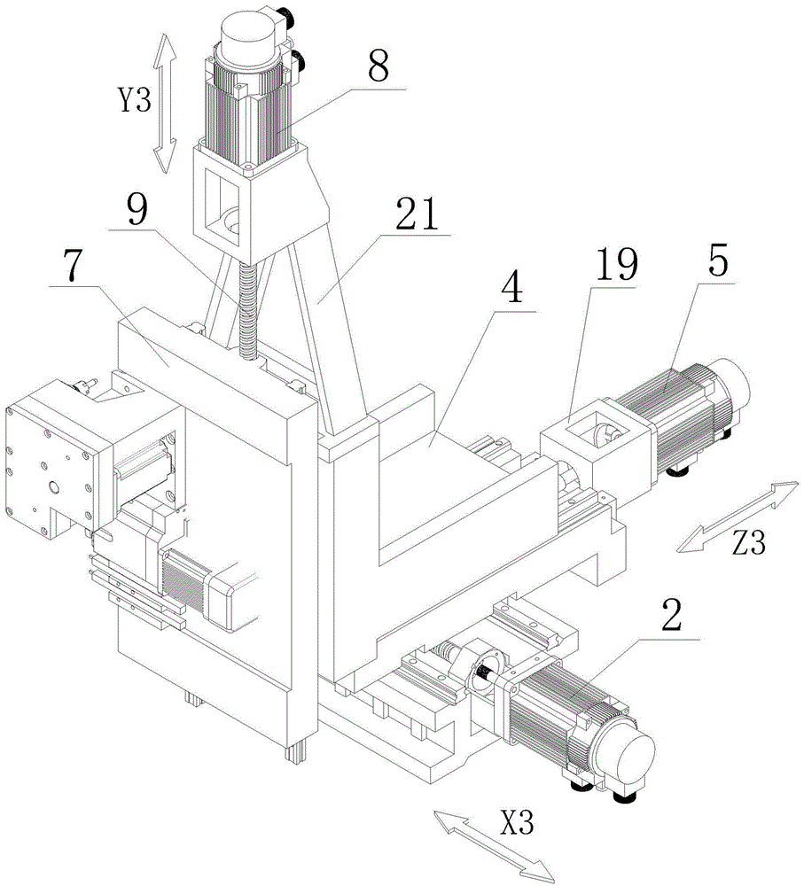
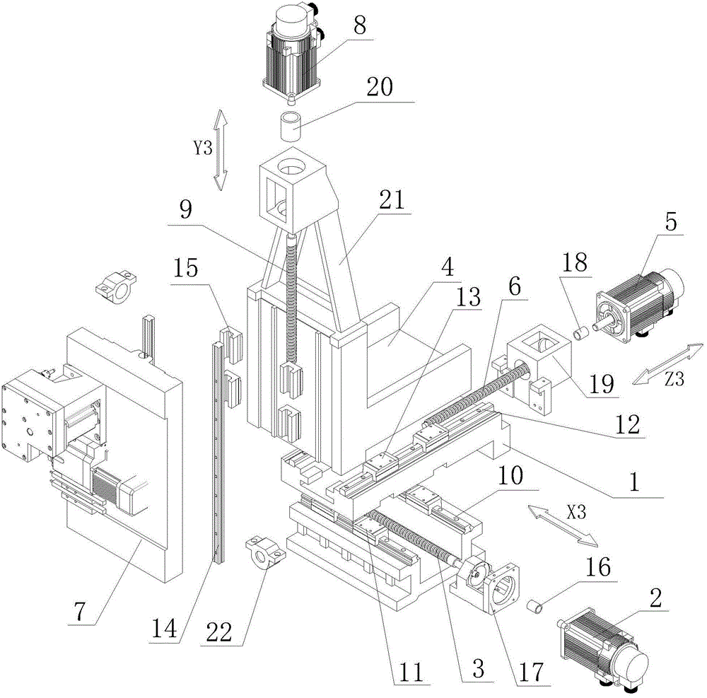
[0045] see Figure 1 to Figure 2 , The third shaft group mechanism of the present invention is composed of three parts: X3 shaft group, Z3 shaft group, and Y3 shaft group.

[0046] The X3-axis group includes an X3-axis rail 10 , an X3-axis slider 11 , an X3-axis slide plate 1 , an X3-axis motor 2 , an X3-axis motor seat 17 and an X3-axis coupling 16 . A base 23 is installed on the machine bed (the base 23 is detachably installed on the machine bed by bolts, or is integrally formed with the machine bed when manufacturing the machine bed), and the X3 axis rail 10 is installed on the base 23, The X3 axis slide block 11 matched with the X3 axis rail 10 is installed on the bottom of the X3 axis slide plate 1 . The X3 axis slide plate 1 is slidably installed on the machine tool through the sliding pair formed by the X3 axis rail 10 and the X3 axis slide block 11 . The bottom of the X3 axis slide plate 1 is equipped with an X3 axis nut, and the X3 axis motor seat 17 is fixed on the...

Embodiment 2

[0050] This embodiment is the same as the X3 axis group and Z3 axis group in Embodiment 1, the difference is that the Y3 axis group includes the Y3 axis rail 14, the Y3 axis slider 15, the tool mounting seat 7 composed of a turret, Y3-axis motor 8, Y3-axis motor seat 21 and Y3-axis coupling 20. The Y3 axis slider 15 is installed on the Z3 axis slide plate 4, the Y3 axis rail 14 is installed on the turret, the Y3 axis nut matched with the Y3 axis screw rod 9 is installed on the turret, and the Y3 axis motor seat 21 is fixed on the Z3 axis slide plate The top of 4 is used to install the Y3-axis motor 8, the Y3-axis motor seat 21 is equipped with a Y3-axis bearing, the Y3-axis screw rod 9 passes through the Y3-axis nut, one end of the Y3-axis screw rod 9 is suspended, and the other end passes through the Y3-axis bearing Be contained in the bearing in the Y3 shaft motor seat 21, and be connected with the power transmission shaft of Y3 shaft motor 8 by Y3 shaft coupling 20. When t...

Embodiment 3

[0052] This embodiment is the same as the X3 axis group and Z3 axis group in Embodiment 1, the difference is that the Y3 axis group includes the Y3 axis rail 14, the Y3 axis slider 15, and the tool composed of the turret and the Y3 axis slide plate. Mounting seat 7, Y3-axis motor 8, Y3-axis motor seat 21 and Y3-axis shaft coupling 20. The Y3 axis slide block 15 is installed on the Z3 axis slide plate 4, the Y3 axis rail 14 is installed on the Y3 axis slide plate, the turret is installed on the Y3 axis slide plate, and the Y3 axis nut matched with the Y3 axis screw rod 9 is installed on the turret. Y3 shaft motor seat 21 is fixed on the top of Z3 shaft slide plate 4, is used to install Y3 shaft motor 8, Y3 shaft bearing is housed in Y3 shaft motor seat 21, Y3 shaft screw mandrel 9 passes Y3 shaft nut, Y3 shaft screw mandrel 9 One end is suspended, and the other end passes through the Y3 shaft bearing and the bearing installed in the Y3 shaft motor seat 21, and is connected with...


PUM


Abstract

The invention discloses a third axis group mechanism on a movable turning-milling machine tool. The third axis group mechanism comprises an X3 axis group, a Z3 axis group and a Y3 axis group, the X3 axis group comprises an X3 axis sliding plate (1), an X3 axis servo motor (2) and an X3 axis lead screw (3), the Z3 axis group comprises a Z3 axis sliding plate (4), a Z3 axis servo motor (5) and a Z3 axis lead screw (6), and the Y3 axis group comprises a tool mounting seat (7), a Y3 axis servo motor (8) and a Y3 axis lead screw (9). The third axis group mechanism has the advantages that the third axis group mechanism is matched with an existing movable turning-milling machine tool, complicated parts can be machined and formed once, and production efficiency is high. Both the bottoms of the X3 axis group and the Z3 axis group are supported, and the third axis group mechanism is more stable in structure and better in rigidity.

Description

technical field [0001] The invention discloses a third shaft group mechanism on a center turning and milling machine tool. Background technique [0002] In the existing centering machine market, there has been research on the technology of machine tool motion axes, and the most widely used one is the three-axis axis group consisting of X1 axis group, Y1 axis group, and Z1 axis group. Axis-centered turning and milling machine (definition: a mechanism including linear rails, slide plates, screw rods, and servo motors is a shaft group. A centering-type turning and milling machine refers to a turning and milling machine that clamps materials forward and backward with a positive axis); or , when the sub-axis structure is added with Z2 axis group, it can be combined with the positive axis structure to form a four-axis center-type turning and milling machine tool; or, when the sub-axis structure composed of X2 axis group and Z2 axis group is combined with the positive axis structur...

Claims


Application Information

Patent Timeline
Patent Type & Authority Applications(China)
IPC IPC(8): B23Q1/46B23Q5/40B23P23/02B23Q5/36B23Q3/155
CPCB23P23/02B23Q1/46B23Q1/626B23Q3/15506B23Q5/36B23Q5/402B23Q5/44B23Q2705/16
Inventor 王建飞
Owner NANJING JIANKE MACHINERY
Why Eureka
Try Eureka