
Combined drive bionic elbow joint

A bionic elbow and compound power technology, applied in manipulators, manufacturing tools, joints, etc., can solve the problems of low motor power, occupy a lot of space, limit the development of joints, etc., and achieve the effect of increasing driving power and saving space.

Inactive Publication Date: 2015-09-09
CHONGQING JIAOTONG UNIVERSITY
View PDF5 Cites 5 Cited by
  • Summary
  • Abstract
  • Description
  • Claims
  • Application Information

AI Technical Summary

Problems solved by technology

[0002] In the current existing joints, the development of the drive has become the top priority of the joint development. The precision of the joint driven by the motor can meet the requirements of the design and use, but the power ratio of the motor is small, and the motor and the reduction transmission device occupy a large Part of the space greatly limits the development of joints; therefore, a compound drive method is needed to increase power and save space

Method used


Image

  • Combined drive bionic elbow joint
  • Combined drive bionic elbow joint

Examples


Embodiment Construction

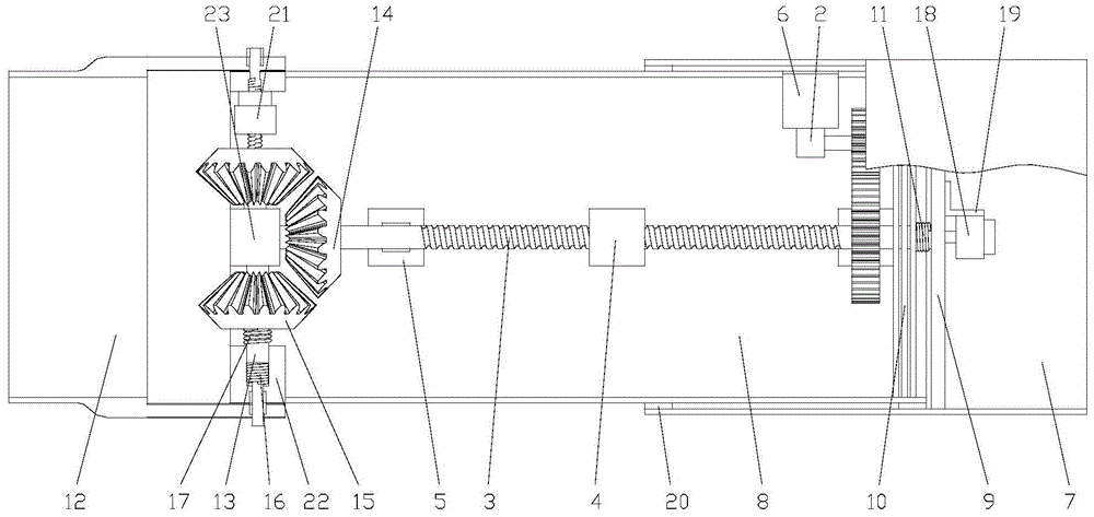
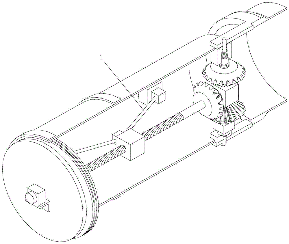
[0015] figure 1 It is the front view of the present invention; figure 2 It is an isometric view of the present invention, as shown in the figure: the compound-driven bionic elbow joint of this embodiment includes a compound power source, a joint housing and a driving part for driving joint movement; the compound power source includes a memory alloy Wire 1 and motor 2; the driving part includes a screw 3 and a slider 4, the screw 3 is driven to rotate by the motor 2, and the memory alloy wire 1 is connected between the slider 4 and the joint housing for along the The screw 3 axially provides force for the slider 4; the slider 4 is connected with the screw 3 to form a screw nut pair, and in the simulation of the rotation and extension and flexion of the elbow joint, the force generated by the phase transition of the memory alloy is used to offset the joint. Most of the force required for movement, while utilizing the self-locking characteristics of the lead screw 3, the joint ...


PUM


Abstract

The invention discloses a combined drive bionic elbow joint. The elbow joint comprises a combined power source, a joint casing and a drive portion for driving the joint to move. The combined power source comprises a memory alloy wire and a motor. The drive portion comprises a lead screw and a sliding block. The lead screw is driven by the motor to rotate, and the memory alloy wire is connected between the sliding block and the joint casing to be used for providing force for the sliding block along the axial direction of the lead screw. According to the elbow joint, the memory alloy and motor combined drive mode is used, large stress produced during deformation of the memory alloy wire is used ingeniously for offsetting most drive force of the joint moving, the joint is driven by the motor to rotate for the required angle accurately, the memory alloy wire and motor perfect combination is achieved, the drive power can be improved, and space is saved.

Description

technical field [0001] The invention relates to a mechanical joint, in particular to a composite drive bionic elbow joint. Background technique [0002] In the current existing joints, the development of the drive has become the top priority of the joint development. The precision of the joint driven by the motor can meet the requirements of the design and use, but the power ratio of the motor is small, and the motor and the reduction transmission device occupy a large Part of the space greatly limits the development of joints; therefore, a compound drive method is required to increase power and save space. Contents of the invention [0003] In view of this, the object of the present invention is to provide a bionic elbow joint with compound drive, which adopts the compound drive mode of memory alloy and motor, skillfully offsets most of the driving force of the joint movement by using the large stress generated when the memory alloy is deformed, and then Using the motor ...

Claims


Application Information

Patent Timeline
IPC IPC(8): B25J17/02
Inventor 罗天洪郭园
Owner CHONGQING JIAOTONG UNIVERSITY
Learn More