LED combined matrix light source for surface detection of heavy rail

A technology of surface detection and combination matrix, which is applied in the field of LED combination matrix light source, can solve the problems of uneven distribution of light brightness and difficulty in accurately detecting the surface of heavy rails, etc., and achieve the effect of good light distribution effect, simple structure and wide application range

Active Publication Date: 2015-09-09
WUHAN UNIV OF SCI & TECH
View PDF2 Cites 1 Cited by
  • Summary
  • Abstract
  • Description
  • Claims
  • Application Information

AI Technical Summary

Problems solved by technology

Since the side surface of the heavy rail is not a single plane, it is composed of multiple curved surfaces. The strip light source directly illuminates the surface of the heavy rail, resulting in uneven distribution of light brightness on the surface of the heavy rail, showing a broken line shape, making A line captured by the line scan camera is not in the same bright area, making it difficult to accurately detect defects on the surface of heavy rails

Method used


Image

  • LED combined matrix light source for surface detection of heavy rail
  • LED combined matrix light source for surface detection of heavy rail
  • LED combined matrix light source for surface detection of heavy rail

Examples


Embodiment 1

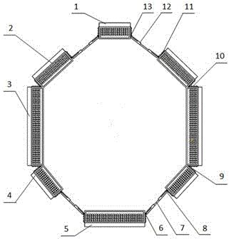
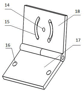
[0038] An LED combination matrix light source for heavy rail surface detection. like figure 1 and Figure 6 As shown, the LED combined matrix light source includes an upper LED matrix light source 1, a lower LED matrix light source 5, two positive side LED matrix light sources 3, two upper side LED matrix light sources 2, two lower side LED matrix light sources 4, two A first telescopic member 7, two second telescopic members 12 and a hinge. The hinges are two first hinges 6, two second hinges 8, two third hinges 9, two fourth hinges 10, two fifth hinges 11 and two sixth hinges Page 13.

[0039] like figure 1 and Figure 6 As shown, the lower LED matrix light source 5 is arranged horizontally, and the upper LED matrix light source 1 is arranged in parallel directly above the lower LED matrix light source 5, and the connecting line between the center of the upper LED matrix light source 1 and the center of the lower LED matrix light source 5 is a lead perpendicular. The...

Embodiment 2

[0051] An LED combination matrix light source for heavy rail surface detection. Except following technical parameter, all the other are with embodiment 1.

[0052] The length of the upper LED matrix light source 1 is 1.07-1.10 times the width of the tread of the heavy rail 25 to be tested.

[0053] The length of the lower LED matrix light source 5 is 1.07-1.10 times the width of the bottom surface of the heavy rail 25 to be tested.

[0054] The length of the positive LED matrix light source 3 is 1.07-1.10 times the height H of the heavy rail 25 to be measured.

[0055] The length of the upper LED matrix light source 2 is 1.07 to 1.10 times the length of the line connecting the neutral axis of the rail waist and the upper end of the rail bottom side of the cross section of the heavy rail 25 to be measured.

[0056] The length of the lower LED matrix light source 4 is 1.07 to 1.10 times the length of the line connecting the neutral axis of the rail waist and the lower end of ...


PUM


Abstract

The invention particularly relates to an LED combined matrix light source for surface detection of a heavy rail. According to the technical scheme, a lower LED matrix light source (5) is horizontally arranged, an upper LED matrix light source (1) is arranged over the lower LED matrix light source (5) in parallel, and the line connecting the center of the upper LED matrix light source (1) and the center of the lower LED matrix light source (5) is a plumb line. Lower side LED matrix light sources (4), front side LED matrix light sources (3) and upper side LED matrix light sources (2) are symmetrically arranged on the two sides of the plumb line in sequence from bottom to top, the line of centers of the two front side LED matrix light sources (3) is a horizontal line, and the horizontal line and the plump line are equally divided by each other. The LED combined matrix light source for surface detection of the heavy rail has the advantages that the structure is simple, illumination is even, the light distribution effect is good, using is easy and convenient, and the application range is wide.

Description

technical field [0001] The invention belongs to the technical field of LED combined matrix light sources. In particular, it relates to an LED combination matrix light source for heavy rail surface detection. Background technique [0002] Machine vision is to use machines instead of human eyes to do various detection, identification and measurement. The machine vision system converts the captured target into an image signal through the image acquisition system (light source, camera, lens, etc.), and transmits it to the image processing system. The image processing system extracts the features of the target based on information such as pixel highlights and color distribution, and makes corresponding judgments, and then controls the on-site equipment according to the results. [0003] Machine vision system has the characteristics of high efficiency and high automation. In the process of mass industrial production, if artificial vision is used to check product quality, the ef...

Claims


Application Information

Patent Timeline
Patent Type & Authority Applications(China)
IPC IPC(8): F21S8/00F21V17/10F21Y101/02
CPCF21S8/00F21V17/10
Inventor 刘灿灿王兴东刘源泂刘钊杨钊朱婷婷郑国石甜黄前德
Owner WUHAN UNIV OF SCI & TECH
Why Eureka
Try Eureka