Combustion furnace and furnace body structure

A furnace body structure and furnace body technology, which is applied in the direction of household stoves/stoves, solid heating fuel, lighting and heating equipment, etc., can solve the problems of increasing wind resistance, poor thermal conductivity of the furnace body, and affecting combustion efficiency, so as to improve installation efficiency, High molding precision and improved heat transfer efficiency

Active Publication Date: 2017-08-08
盛火电商宜昌有限公司
View PDF7 Cites 0 Cited by
  • Summary
  • Abstract
  • Description
  • Claims
  • Application Information

AI Technical Summary

Problems solved by technology

The problem is that the processing cost is high, especially the welding process cost is high, and the site environment is poor, the labor intensity of the workers is high, and the production efficiency is low
[0003] The material of the existing furnace body is mostly steel plate and cast iron. The thermal conductivity of the furnace body is poor, and the problem of uneven heat distribution on the furnace body often occurs. For example, the temperature difference between the position near the chimney and the position near the feeding channel is 30- 50 degrees
In order to improve the heating effect, it is necessary to set up a turnback structure in the flue, which increases the wind resistance and affects the combustion efficiency

Method used


Image

  • Combustion furnace and furnace body structure
  • Combustion furnace and furnace body structure
  • Combustion furnace and furnace body structure

Examples


Embodiment 1

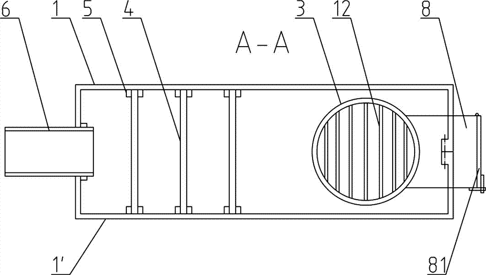
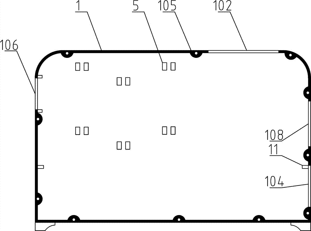
[0041] Such as figure 1 , 11 In 12, a furnace body structure, the furnace body is divided into multiple parts by a vertically split structure, and the parts are connected by connecting pieces. The vertical split structure is adopted, and each split structure is easy to demould. Thereby, a furnace body with higher precision can be obtained, so as to facilitate the later installation. Commonly used structures on the furnace body, such as chimney mouth 106, fire outlet 102, feed inlet 108, ash hopper or air inlet 104, etc., can be passed through once. Casting or die-casting saves the cutting, welding and grinding processes in the later stage, greatly improves labor efficiency and reduces labor intensity.

[0042] Preferably, the division is performed from the position of the midline. Dividing the furnace body into opposing first furnace body 1 and second furnace body 1' by adopting a vertically split structure from the center line;

[0043] The connection mode between the fir...

Embodiment 2

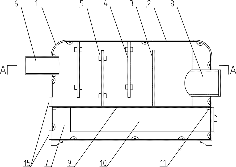
[0063] On the basis of embodiment 1, a kind of combustion furnace adopting above-mentioned furnace body structure is provided with dividing plate 9 in the furnace body, and dividing plate isolates the lower space of furnace body into ash cavity 7, and furnace hearth 3 is positioned at the space of dividing plate 9 in furnace body Above, the inner chamber of the furnace 3 communicates with the ash chamber 7;

[0064] A channel for flue gas to pass is provided between the top of the furnace 3 and the top inner side of the furnace body; a feed channel 8 and a chimney connecting pipe 6 are provided in the furnace body.

[0065] The furnace body is made of aluminum, aluminum alloy or titanium alloy. For the occasions requiring larger firepower, the smoke baffle 4 may not be provided, so as to improve the combustion efficiency under the premise of ensuring the heating effect.

[0066] In a preferred solution, the furnace is a coal furnace 31 made of refractory mud with a thickness ...

Embodiment 3

[0069] On the basis of Embodiments 1 and 2, preferably, the first furnace body 1 and the second furnace body 1' are made of aluminum alloy and have a bisected structure. The first furnace body 1 and the second furnace body 1' are connected by means of interlaced extensions 111 and countersunk bolts. A bite 110 is provided on the end surface where the first furnace body 1 and the second furnace body 1' contact.

[0070] Preferably, the bottom is connected by means of connecting plate 112 and bolts and nuts.

[0071] A fire outlet 102 is provided on the top of the furnace body composed of the first furnace body 1 and the second furnace body 1 ′, and a sliding or rotating fire sealing plate is provided at the position of the fire outlet 102 .

[0072] The inner walls of the first furnace body 1 and the second furnace body 1' are provided with a grid structure 103 or fins 107, and a plurality of supporting blocks 11 are also provided for supporting cast iron or steel partitions 9...


PUM


Abstract

Disclosed is a furnace body structure. The furnace body is divided into a plurality of portions through a vertical division structure; every two adjacent portions are connected through a connecting part; the furnace body is provided with a chimney opening, a fire outlet, a feeding inlet and an ash hopper or an air inlet; the inner wall of the furnace body is provided with a separation plate which is formed in a one-step mode and is roughly horizontal or the inner wall of the furnace body is provided with a supporting block which is used for supporting the separation plate which is roughly horizontal. The invention also provides a combustion furnace with the furnace body structure. The separation plate is arranged in the furnace body; the lower portion space of the furnace body is isolated into an ash chamber through the separation plate; a combustion chamber is located above the separation plate which is arranged in the furnace body; an inner chamber of the combustion chamber is communicated with the ash chamber; a channel for the flus gas to pass through is formed between the top of the combustion chamber and the inner side of the top of the furnace body; the furnace body is provided with a feeding channel and a chimney connection pipe. According to the combustion furnace and the furnace body structure, the vertical division structure is adopted and accordingly the stripping of every structural portion in the furnace body is facilitated, the one-step forming through a die is facilitated, the forming accuracy is high, and the installation efficiency of the integral combustion furnace is greatly improved.

Description

technical field [0001] The invention relates to the field of civil combustion furnaces, in particular to a combustion furnace using firewood, bellflower or coal as fuel and a furnace body structure. Background technique [0002] Existing combustion furnaces, such as more energy-saving return air furnaces, gasifiers or return air gasification furnaces, are usually welded by bending steel plates, or cast in sections from top to bottom, and then welded or bolted. become. The existing problem is that the processing cost is high, especially the welding process cost is high, and the site environment is poor, the labor intensity of workers is high, and the production efficiency is low. [0003] The material of the existing furnace body is mostly steel plate and cast iron. The thermal conductivity of the furnace body is poor, and the problem of uneven heat distribution on the furnace body often occurs. For example, the temperature difference between the position near the chimney an...

Claims


Application Information

Patent Timeline
Patent Type & Authority Patents(China)
IPC IPC(8): F24B1/02F24B1/191
CPCF24B1/02F24B13/00
Inventor 高洪亮
Owner 盛火电商宜昌有限公司
Why Eureka
Try Eureka