Dynamic tension experiment fixture

A dynamic stretching and experimental technology, applied in the field of material mechanics experimental research, can solve the problems of complex and time-consuming preparation process, and achieve the effect of simple processing technology, avoiding stress concentration, and convenient clamping.

Inactive Publication Date: 2015-09-09
NANJING UNIV OF SCI & TECH
View PDF4 Cites 12 Cited by
  • Summary
  • Abstract
  • Description
  • Claims
  • Application Information

AI Technical Summary

Problems solved by technology

[0003] Usually, the dynamic tension experiment completed by the separate Hopkinson tie rod device is basically to prepare double-threaded specimens and then perform high strain rate experiments, such as the literature "Fransplass H, Langseth M, Hopperstad O S. Tensile behavior of threaded steel fasteners at elevated rates of strain[J].International Journal of Impact Engineering,2011,53(11):946–957.” and “Feng F, Huang S, Meng Z, et al. Experimental study on tensile property of AZ31B magnesium alloy at different high strain rates and temperatures[J].Materials&Design,2014,57(5):10–20.”, the thread processing makes the preparation process of the specimen complicated and time-consuming; or the literature “Xu Z, Li Y.A novel method in determination of dynamic fracture toughness under mixed mode I / II impact loading[J].International Journal of Solids&Structures,2012,49:366–376.”A method in which holes and pins are fixed on the specimen Compared with the former method, although the required experimental samples are easier to process, problems such as stress concentration caused by opening holes and the generation and expansion of micro-cracks cannot be avoided.

Method used


Image

  • Dynamic tension experiment fixture
  • Dynamic tension experiment fixture
  • Dynamic tension experiment fixture

Examples


Embodiment Construction

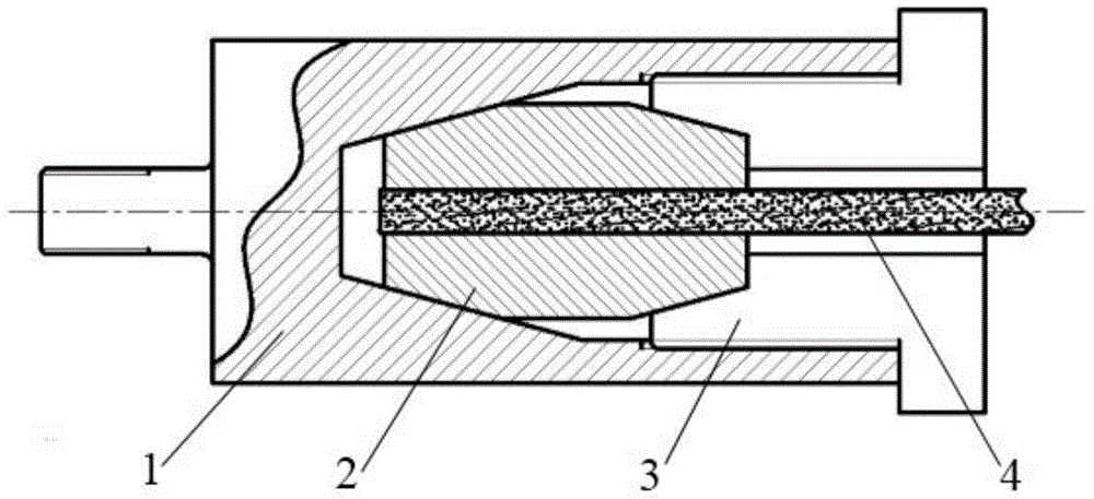
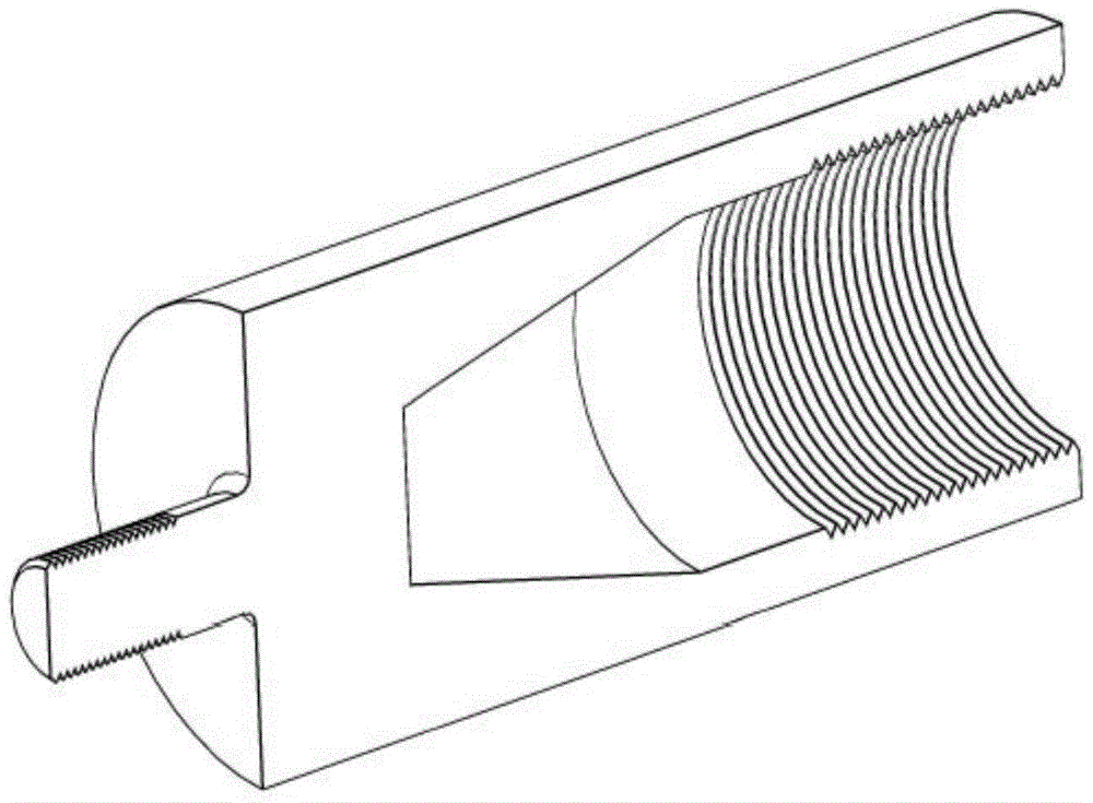
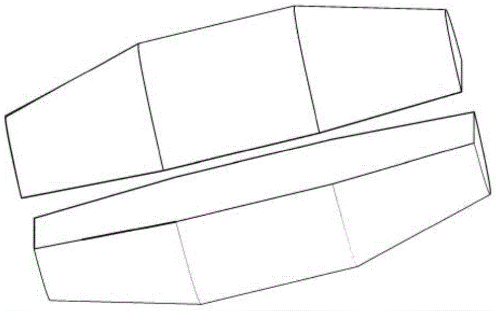
[0017] combine Figure 1 to Figure 4 :

[0018] The present invention is a kind of fixture for dynamic tension experiment, which comprises main fixture 1, clip 2 and thread fixing fixture 3, wherein, one end of main fixture 1 is provided with the external thread that is configured to be connected with the Hopkinson rod, and the other end is opened The inner wall of the hole is provided with an internal thread and an internal tapered surface sequentially from the outside to the inside, and the outer circumference of one end of the threaded fixture 3 is provided with an external thread that matches the internal thread of the main fixture 1, and the threaded fixture 3 is provided along the axis. The central hole through which the lath-shaped test piece 4 passes, and a tapered hole coaxial with the central hole and whose minimum diameter is larger than the central hole is opened at one end extending into the main fixture 1. Two symmetrical clips 2 are configured for For clamping ...


PUM


Abstract

The invention discloses a dynamic tension experiment fixture. The dynamic tension experiment fixture comprises a main fixture, clamping pieces and a thread fixing fixture, wherein a hole is formed in one end of the main fixture; an internal thread and an internal conical surface are sequentially formed on the inner wall of the hole from outside to inside; an external thread matched with the internal thread of the main fixture is formed on the periphery of one end of the thread fixing fixture; a center hole allowing a lath-shaped test piece to pass through is formed along an axis of the thread fixing fixture, a taper hole coaxial with the center hole is formed in one end, extending into the main fixture, of the thread fixing fixture, and the minimum aperture of the taper hole is larger than the center hole; the two symmetric clamping pieces are configured and used for clamping the lath-shaped test piece, and shapes of two ends of each clamping piece are matched with the shape of the internal conical surface of the main fixture and the shape of taper hole of the thread fixing fixture respectively. The test piece is simple to process, the clamping operation is convenient, the experiment efficiency is high, and the dynamic tension experiment fixture can be applicable to test pieces with different thicknesses.

Description

technical field [0001] The invention belongs to the technical field of material mechanics experiment research, in particular to a dynamic tensile experiment fixture. Background technique [0002] In recent years, with the improvement of Split Hopkinson Torsion Bar (SHTB) technology, the split Hopkinson test device has become an important means to study the dynamic mechanical properties of materials. It is based on the theory of one-dimensional stress wave , to obtain the dynamic mechanical behavior of materials through experiments at different strain rates, which has aroused widespread concern in the engineering community. [0003] Usually, the dynamic tension experiment completed by the separate Hopkinson rod device is basically to prepare double-threaded specimens and then perform high strain rate experiments, such as the literature "Fransplass H, Langseth M, Hopperstad O S. Tensile behavior of threaded steel fasteners at elevated rates of strain[J].International Journal ...

Claims


Application Information

Patent Timeline
Patent Type & Authority Applications(China)
IPC IPC(8): G01N3/04
Inventor 蒋晶陈雄许进升张中水贾登余家泉
Owner NANJING UNIV OF SCI & TECH
Why Eureka
Try Eureka