
Micro-amplitude impact wear test device and test method based on controlled impact energy

A technology of wear test and impact energy, which is applied in the direction of testing wear resistance, etc., can solve the problems of low efficiency, low degree of automation and low frequency of impact wear test, and achieve novelty and creativity, high practicability and low manufacturing cost Effect

Active Publication Date: 2017-08-04
SOUTHWEST JIAOTONG UNIV
View PDF6 Cites 1 Cited by
  • Summary
  • Abstract
  • Description
  • Claims
  • Application Information

AI Technical Summary

Problems solved by technology

At present, the current impact and wear testing machine has a low degree of automation, and it is generally based on force control to study impact wear, and impact wear is a process of energy conversion. Therefore, this type of device cannot comprehensively study impact wear behavior.
In addition, the existing impact wear testing machine based on controlled energy has low degree of automation and low frequency (only a few tenths of Hz), resulting in low impact wear test efficiency

Method used


Image

  • Micro-amplitude impact wear test device and test method based on controlled impact energy
  • Micro-amplitude impact wear test device and test method based on controlled impact energy
  • Micro-amplitude impact wear test device and test method based on controlled impact energy

Examples


Embodiment

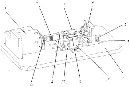
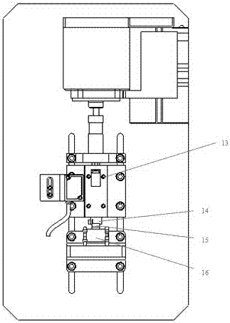
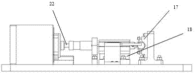
[0040] Such as Figures 1 to 7 As shown, this embodiment provides a micro-impact wear test device based on the control of impact energy, the test device mainly includes a driving motor, a damping punch, a pull rod, a limit block, an energy block, a linear rolling unit and its fixing plate , Sample clamping bottom plate, installation bottom plate and other components. Wherein, the driving motor is preferably a voice coil motor, which is the power supply unit of the entire test device, and the driving motor is controlled by a motor control system, which can control the operating frequency, operating amplitude and operating speed curve type of the voice coil motor, It has the advantages of high degree of digitalization and operability, and can meet the test requirements of different frequencies, different speeds and different loading curves.

[0041] The installation bottom plate provides installation space for other components in the test device. The middle part of the installa...


PUM

PropertyMeasurementUnit
friction coefficientaaaaaaaaaa

Abstract

The invention discloses a micro-impact wear test device based on the control of impact energy, which solves the problem of deficiencies in the current research methods of impact wear. The micro-impact wear test device based on controlled impact energy includes a driving motor, a damping punch driven by the driving motor, a pull rod connected to the damping punch at one end, located at the other end of the pull rod and under the action of the pull rod An energy block capable of linear motion, a magnetic scale arranged on one side of the energy block, a magnetic scale reading head used in conjunction with the magnetic scale, a block clamp connected to the energy block, and a magnetic scale located on the side of the energy block The direction of the end of the energy block and the sample clamping base plate on which the tube clamp is fixed. The invention adopts the design of controlling the energy of the energy block by controlling the speed, realizes the study of micro-impact wear from the perspective of energy, and effectively overcomes the defects of the existing study of micro-impact wear from the perspective of force.

Description

technical field [0001] The invention relates to an impact wear test device, in particular to a test device and a test method for studying micro-impact wear by controlling impact energy. Background technique [0002] Impact wear is the surface wear caused by repeated dynamic contact and impact between two solid surfaces. In all kinds of machinery, many parts are subjected to different degrees of impact wear, and the failure of mechanical parts caused by impact fretting wear widely exists in the fields of electric power, petrochemical, mining machinery, marine machinery, aerospace, etc. Bring bigger energy waste, brought huge loss to people's property security and national economy. Shock loads can cause damage to contact surfaces and, in severe cases, lead to failure of machine components. Of the types of wear failure, impact wear is probably the most materially detrimental and least understood type of wear. In order to study this kind of wear, so far, many types of testing...

Claims


Application Information

Patent Timeline
Patent Type & Authority Patents(China)
IPC IPC(8): G01N3/56
Inventor 蔡振兵林映武陈志强彭金方朱旻昊周仲荣
Owner SOUTHWEST JIAOTONG UNIV
Learn More