On-chip antenna test device

A test device, on-chip antenna technology, applied in the direction of the antenna radiation pattern, etc., can solve the problems of test error, small interface size, influence of the overall structure of the antenna electrical performance, etc., to achieve the effect of improving stability, reducing influence and maintaining stability

Active Publication Date: 2015-09-09
CHINA ELECTRONIS TECH INSTR CO LTD
View PDF3 Cites 22 Cited by
  • Summary
  • Abstract
  • Description
  • Claims
  • Application Information

AI Technical Summary

Problems solved by technology

[0007] At present, with the development of antenna technology, a type of probe-fed on-chip antenna has emerged. With the rapid development of wireless communication, the current test requirements for on-chip antennas are becoming increasingly urgent. Due to the different feeding methods of on-chip antennas, especially In the millimeter wave frequency band, the feed interface is changed from the traditional coaxial waveguide feed to the GSG probe feed, and because the interface size is very small, it must cooperate with CCD and high-preci

Method used


Image

  • On-chip antenna test device
  • On-chip antenna test device
  • On-chip antenna test device

Examples


Embodiment Construction

[0032] The following will clearly and completely describe the technical solutions in the embodiments of the present invention with reference to the accompanying drawings in the embodiments of the present invention. Obviously, the described embodiments are only some, not all, embodiments of the present invention. Based on the embodiments of the present invention, all other embodiments obtained by persons of ordinary skill in the art without making creative efforts belong to the protection scope of the present invention.

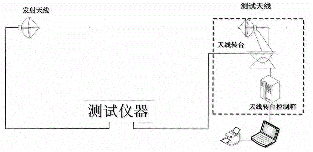
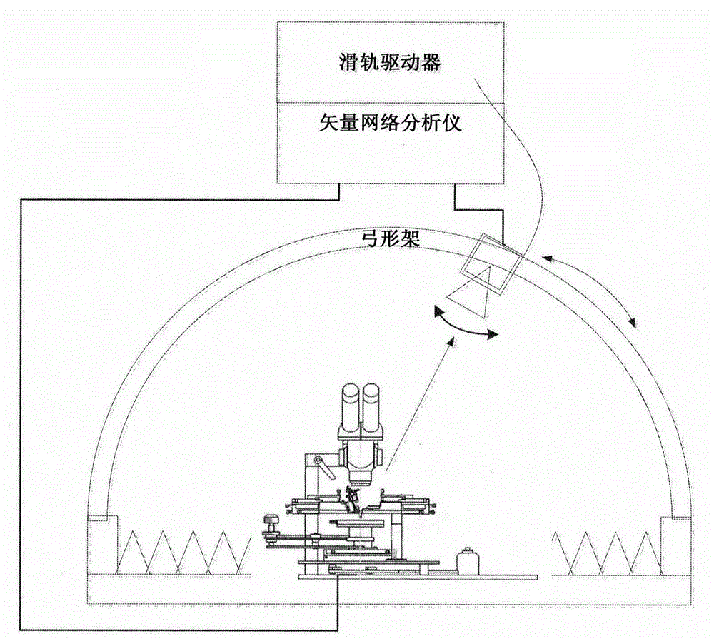
[0033] Due to the different feeding methods of the on-chip antenna, especially in the millimeter wave frequency band, the feeding interface is changed from the traditional coaxial waveguide feeding to the GSG probe feeding, and because the interface size is very small, it must cooperate with CCD and high-precision adjustment The device can complete the feeding action, so the traditional connection method can no longer meet the test requirements of the on-chip a...


PUM


Abstract

The invention provides an on-chip antenna test device. An adjusting mechanism is arranged on a probe bench pedestal and is formed by X, Y, and Z mobile platforms. Antennas on an antenna chip-bearing bench are precisely positioned via a CCD telescope and the adjusting mechanism. A probe support performs feeding for the on-chip antennas. Via the rotation of a low-position axis and a polarization axis, matching for polarization of a receiving antenna and an emission antenna is performed. If the polarization of the receiving and emission antennas is matched, full-directional data acquisition in 0-360 DEG is performed via a rotation shaft. In the low-direction axis, a direct-current servo motor drives a synchronous tooth belt wheel which drives a turbine worm. The turbine worm drives a straight gear which drives a sliding guide rail. According to the invention, a feeding problem of the antennas is solved; the test device is provided with front and back testing ability of the antenna; effects of interference on antennas of a traditional bench body are reduced; and testing functions of holographic stereoscopic directional diagram of a to-be-tested antenna is achieved.

Description

technical field [0001] The invention relates to the technical field of testing, in particular to an on-chip antenna testing device. Background technique [0002] Modern antenna measurement is based on computer applications, mainly including far-field measurement, near-field measurement, and compact field measurement, including antenna principles, mechanical control, high-performance instruments, computer software, and data processing. , Efficiency, intelligence and automation are the general trend of antenna measurement technology development. [0003] The antenna far-field measurement refers to directly obtaining the far-field performance parameters of the antenna in the radiation far-field area of ​​the antenna. In general, the antenna far-field test distance R needs to satisfy R≥2D 2 / λ, D is the maximum size of the antenna aperture, and λ is the working wavelength of the antenna. The traditional far-field antenna test device is mainly a test turntable. According to th...

Claims


Application Information

Patent Timeline
IPC IPC(8): G01R29/10
Inventor 赵锐王亚海
Owner CHINA ELECTRONIS TECH INSTR CO LTD
Why Eureka
Try Eureka