
Laser light source device and projection display device

A laser light source, laser beam technology, applied in projection devices, optics, optical components, etc., can solve the problems of homogenizer damage and laser beam leakage, and achieve the effect of preventing leakage

Active Publication Date: 2017-08-04
RICOH KK
View PDF2 Cites 0 Cited by
  • Summary
  • Abstract
  • Description
  • Claims
  • Application Information

AI Technical Summary

Problems solved by technology

[0008] However, if for some reason the homogenizer is broken or falls off from the specified position, the laser beam will still leak out in the interference state

Method used


Image

  • Laser light source device and projection display device
  • Laser light source device and projection display device
  • Laser light source device and projection display device

Examples


Embodiment Construction

[0025] Embodiments of the present invention are described below.

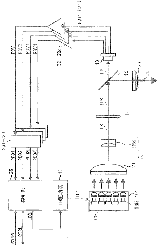
[0026] figure 1 It is a schematic diagram of the first embodiment of the laser light source device of the present invention.

[0027] figure 1 Reference numeral 10 in the middle indicates an LD module, numeral 11 indicates an LD drive unit, and numeral 12 indicates a beam combining optical system.

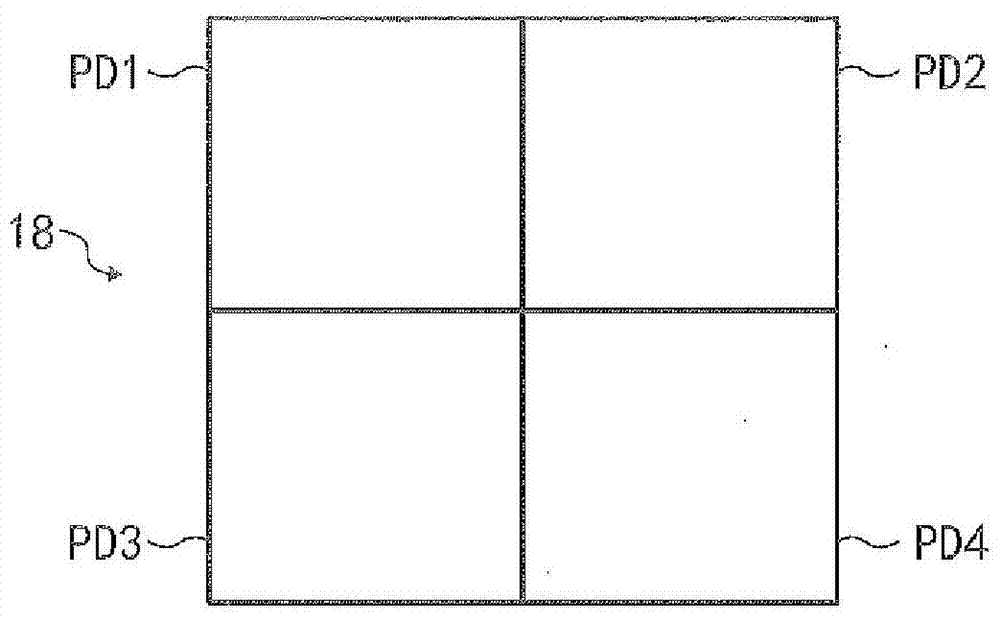
[0028] Reference numeral 14 indicates a homogenizer, reference numeral 16 indicates a light separation unit, reference numeral 18 indicates a light detection unit, and reference numeral 20 indicates an emission optical unit.

[0029] Reference numerals 221 to 224 indicate amplifiers, reference numerals 231 to 234 indicate digital-to-analog converters (hereinafter referred to as ADCs), and reference numeral 25 indicates a control unit.

[0030] The LD module 10 has a plurality of LDs (semiconductor lasers) 100 and collimator mirrors 101 respectively combined with the plurality of lasers.

[0031] Each set of LD 1...


PUM


Abstract

The present invention relates to a laser light source device and a projection display device, and aims to provide a new type of laser light source that can effectively prevent laser beams from leaking in an interference state. The laser light source device of the present invention has a laser light source (10, 11, 12) that synthesizes multiple laser beams into a laser beam, a homogenizer (14) that eliminates or reduces the coherence of the laser beam emitted by a small light source, The laser beam from the homogenizer (14) is emitted to the external output optical system (20), and a part of the beam separated from the laser beam emitted from the homogenizer (14) to the output optical system (20) is used as the laser beam for detection. A light separation part (16), a light detection part (18) having a plurality of light receiving parts for receiving the detection laser beam separated by the light separation part (16), and a plurality of light receiving parts based on the light detection part (18) output to control the light emission control unit (25) of the laser light source to emit light.

Description

technical field [0001] The invention relates to a laser light source device and a projection display device. Background technique [0002] A projection display device is a device that irradiates an image displayed on an image display element with illumination light emitted by a laser light source device, and uses a projection optical system to amplify and project the light modulated based on the image. Projection display devices have been widely used in recent years. [0003] Various lighting devices, such as transmissive or reflective liquid crystal panels, digital micromirror devices (hereinafter referred to as DMDs), etc., are used as image display elements. [0004] On the other hand, as the size of the projected image screen increases, a large amount of illumination light for illuminating the image display element is required. Conventionally, as disclosed in Patent Document 1 (JP-A-2012-141581), laser beams are combined by combining multiple laser beams to obtain a la...

Claims


Application Information

Patent Timeline
Patent Type & Authority Patents(China)
IPC IPC(8): G03B21/20
CPCG03B21/2013G03B21/2033G03B21/204G03B21/2053G03B21/208G02B27/48G03B21/2086G02B5/02G02B27/09
Inventor 村井俊晴藤田和弘高桥达也西森丈裕
Owner RICOH KK
Learn More