Cable stayed bridge for test, and mounting method

A cable-stayed bridge and testing technology, applied in educational appliances, instruments, teaching models, etc., can solve the problems of difficult to simulate the mechanical performance of the cable-stayed cable, the overall scale and difficulty are large, and the lateral scale is not reduced. Crossing of prestressed pipes, which is beneficial to the adjustment of cable force, and the effect of convenient disassembly and assembly

Active Publication Date: 2015-09-09
CHANGSHA UNIVERSITY OF SCIENCE AND TECHNOLOGY
View PDF19 Cites 6 Cited by
  • Summary
  • Abstract
  • Description
  • Claims
  • Application Information

AI Technical Summary

Problems solved by technology

[0004] For the small-scale cable-stayed bridge model test, it simulates the elastic mechanical performance of the cable-stayed bridge system. Due to the size effect and the use of different materials, it is impossible or difficult to simulate the mechanical performance of the elastic system supported by the cable-stayed cables after cracking. And it is impossible to know the ultimate resistance of the structural system
For the scale model of large-scale cable-stayed bridges, the force of the cable-stayed cables is simulated by elastic support and tensioned steel strands, which simulates the force of the main girder under the elastic system to a certain extent, but it is difficult to accurately simulate the main girder The mechanical performance after cracking, and it is difficult to simulate the mechanical

Method used


Image

  • Cable stayed bridge for test, and mounting method
  • Cable stayed bridge for test, and mounting method
  • Cable stayed bridge for test, and mounting method

Examples


Embodiment Construction

[0039] Embodiments of the present invention will be further described in detail below in conjunction with the accompanying drawings and examples. The following examples are used to illustrate the present invention, but should not be used to limit the scope of the present invention.

[0040] In the description of the present invention, unless otherwise specified, "plurality" means two or more; unless otherwise specified, "notch-shaped" means a shape other than an even cross-section. The orientation or positional relationship indicated by the terms "upper", "lower", "left", "right", "inner", "outer", "front end", "rear end", "head", "tail" etc. is Based on the orientation or positional relationship shown in the drawings, it is only for the convenience of describing the present invention and simplifying the description, and does not indicate or imply that the referred device or element must have a specific orientation, be constructed and operated in a specific orientation, and th...


PUM

PropertyMeasurementUnit
Thicknessaaaaaaaaaa

Abstract

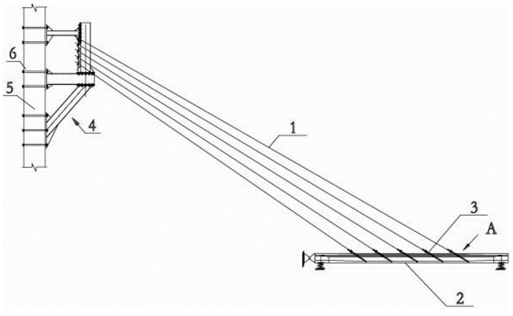
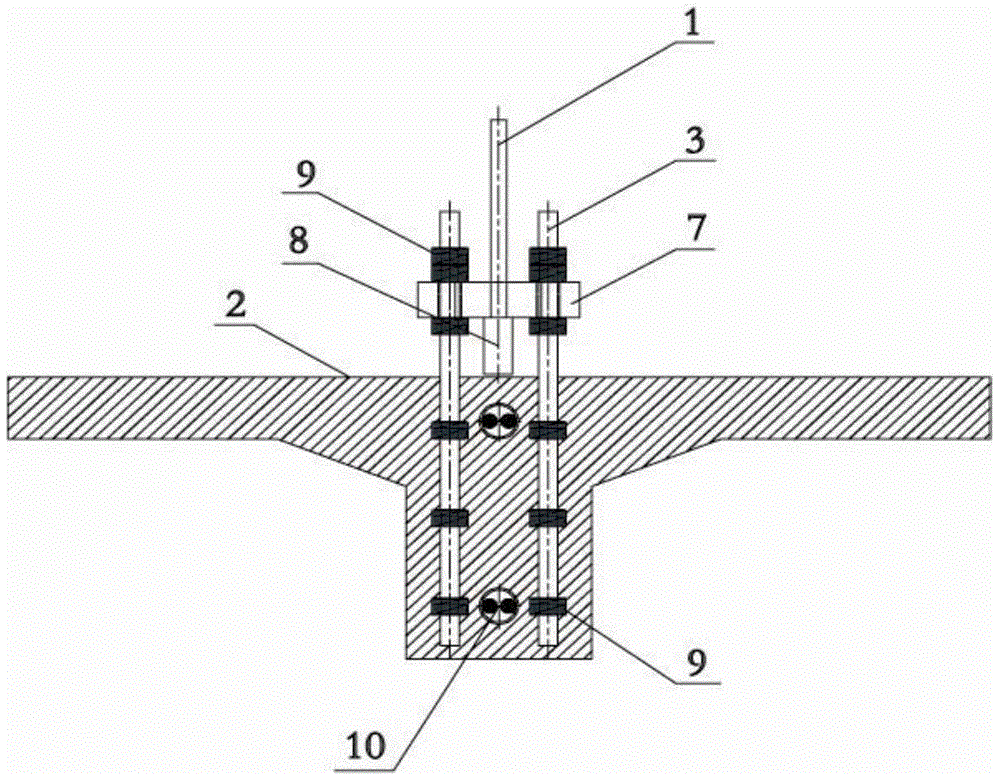
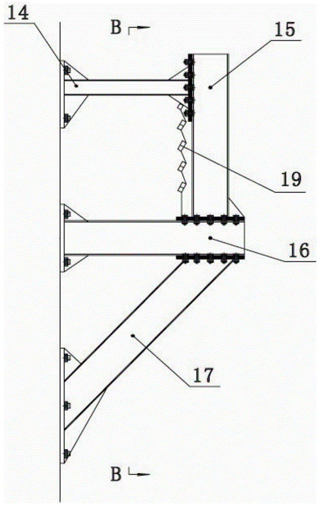
The invention relates to the technical field of bridge tests, and especially relates to a cable stayed bridge for tests, and a mounting method. The cable stayed bridge comprises a horizontal main beam, a vertical shear wall and multiple inclined stay cables. Two ends of each inclined stay cable are fixedly anchored to the main beam and the shear wall. Multiple embedded parts are pre-embedded inside the main beam at certain intervals. Each embedded part is detachably connected to a connection plate. The connection plates are fixedly anchored to the inclined stay cables. The test scale, the loading difficulty and the test cost are effectively reduced, the reduced scale proportion of a model can be increased, the bridge is convenient to dismount and assemble, and cable forces can be leveled during a test. During a mounting process, people do not need to damage the main beam structure, the inclined stay cables are effectively preventing from crossing pre-stress pipelines inside the main beam, the overall force bearing of the main beam and the force bearing paths of the inclined stay cables will not be changed, the force bearing performance of the main beam and the inclined stay cables can be truly simulated, and the force bearing performance and the limit force resistance of the inclined stay cables and the main beam after the main beam breaks and stays in a force bearing state can be accurately simulated.

Description

technical field [0001] The invention relates to the technical field of bridge tests, in particular to a test cable-stayed bridge and an installation method. Background technique [0002] The cable-stayed bridge has the characteristics of beautiful appearance, strong spanning ability, flexible span layout and less construction interference, and has good mechanical properties and economic indicators. Therefore, since the 1950s, modern cable-stayed bridges have developed rapidly, with ever-increasing spans and increasingly diversified structural forms. In order to better study the mechanical performance of the cable-stayed bridge in the laboratory, it is necessary to truly restore the force of the cable-stayed bridge in the laboratory. [0003] At present, the model tests of cable-stayed bridges in scientific research tests are relatively complicated, with complex mechanical properties, mainly compression-bending members. The anchorage method of the beam is generally directly...

Claims


Application Information

Patent Timeline
IPC IPC(8): G09B25/04
CPCG09B25/04
Inventor 颜东煌黄筱淇刘昀潘权许红胜彭卓
Owner CHANGSHA UNIVERSITY OF SCIENCE AND TECHNOLOGY
Why Eureka
Try Eureka