Nonlinear magnetic resistance-enhanced magnetic sensor device and preparation method thereof
A magnetic sensor, non-linear technology, applied in the manufacture/processing of magnetic field controlled resistors, electromagnetic devices, etc., can solve the problems of low room temperature magnetoresistance, large magnetic field, hindering applications, etc., and achieve a wide range of practical prospects. The effect of moderate raw material price and excellent magnetic resistance performance
- Summary
- Abstract
- Description
- Claims
- Application Information
AI Technical Summary
Problems solved by technology
Method used
Image
Examples
Embodiment 1
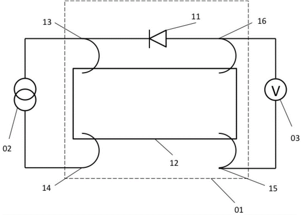
[0033] The monocrystalline silicon chip of the thermal oxide layer with a thickness of 500nm is cleaned, and the strip-shaped MgO-CoFeB-Ta structure magnetic film material 12 ( figure 1 ), and deposit a layer of SiO on the outermost layer 2 as a protective layer. Then annealing is carried out at a certain temperature to achieve good vertical anisotropy. The method of ultrasonic pressure welding is used to draw four lead wires respectively on the four corners of the strip-shaped magnetic metal multilayer film. Finally, between electrodes 13 and 16 according to figure 1 A zener diode 11 is shown connected. So far, a nonlinear enhanced magnetoresistive magnetic sensor device 01 has been prepared.
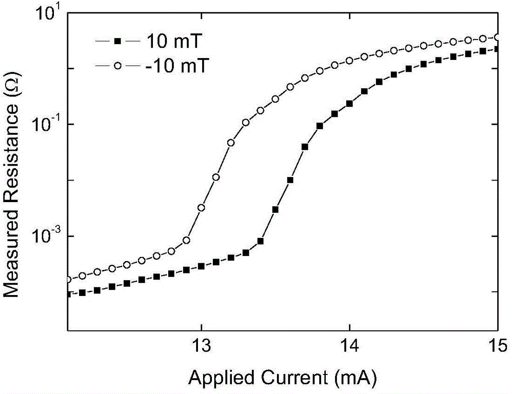
[0034] The prepared magnetic thin film material 12 is structurally characterized by TEM (JEOL-2011), showing that it is a polycrystalline structure; figure 1 In the four-electrode method shown, Keithley2400 power meter 02 provides constant current from two electrodes 13 and 14 on ...
Embodiment 2
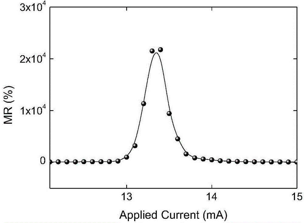
[0037] With the magnetic sensor device 01 of the nonlinear enhanced magnetoresistance prepared in the same method as in Example 1, and using the same magnetoelectric measurement method as in Example 1, at room temperature (300K), under the condition of a loading current of 13.4mA, change Magnetic field, to measure magnetoelectric transport properties. Here, the magnetoresistance is defined as MR(B)=[R(B)-R + / R + ]×100%, where R(B) and R+ Respectively represent the resistance value under the external magnetic field B and the positive saturation magnetic field when the current is 13.4mA. According to this definition, the maximum reluctance of this device can reach 23,000%, and the working magnetic field range can be between ±1mT (such as Figure 4 ). At the time of magnetic reversal, the maximum magnetic sensitivity reaches 1.7×10 5 % / mT (such as Figure 4 ), much higher than the existing magnetoresistive magnetic sensors.
Embodiment 3
[0039] On the basis of the non-linear enhanced magnetoresistance magnetic sensor device 01 in the first embodiment, the programmable magnetoelectric logic operation is realized by utilizing its special magnetoelectric symmetry through structural improvement.
[0040] Adopt the vertical magnetization magnetic thin film material 12 prepared by the same process as in Example 1, add Zener diode 11 and switch 18 between electrodes 13 and 16, add Zener diode 11 and switch 20 between electrodes 14 and 15 , the method of magnetoelectric measurement is the same as that of embodiment 1. So far, a programmable magnetoelectric logic device 04 based on a nonlinear enhanced magnetoresistive magnetic sensor device has been prepared ( Figure 5 ).
[0041] When the switch 18 is in the on state and the switch 20 is in the off state, we define it as configuration A, and the programmable magnetoelectric logic device 04 will degenerate into the nonlinear enhanced magnetoresistive magnetic sensor...
PUM
| Property | Measurement | Unit |
|---|---|---|
| Resistance | aaaaa | aaaaa |
Abstract
Description
Claims
Application Information
 - R&D
- Intellectual Property
- Life Sciences
- Materials
- Tech Scout
- Unparalleled Data Quality
- Higher Quality Content
- 60% Fewer Hallucinations
Browse by: Latest US Patents, China's latest patents, Technical Efficacy Thesaurus, Application Domain, Technology Topic, Popular Technical Reports.
© 2025 PatSnap. All rights reserved.Legal|Privacy policy|Modern Slavery Act Transparency Statement|Sitemap|About US| Contact US: help@patsnap.com


