Transmission mechanism for permanent magnetic gear

A gear transmission, permanent magnet technology, applied in the direction of electromechanical transmission, electromechanical devices, electric components, etc., can solve the problems of the output speed cannot be constant, the output speed fluctuates, only the speed can be changed, etc., to increase the processing cost and manufacturing difficulty, operation Reliability reduction, permanent magnet saving effect

Inactive Publication Date: 2015-09-09
DALIAN JIAOTONG UNIVERSITY
View PDF5 Cites 7 Cited by
  • Summary
  • Abstract
  • Description
  • Claims
  • Application Information

AI Technical Summary

Problems solved by technology

[0010] The disadvantages of the existing concentric permanent magnet gear transmission: (1) one rotor must be fixed in the three-layer concentric rotor, that is, there can only be two moving rotors during operation, so the transmission ratio is fixed; (2) when the input speed When fluctuations occur (such as wind power generation), the output speed also fluctuates accordingly, that is, the output speed cannot be constant; (3) only speed can be changed, but speed cannot be adjusted

Method used


Image

  • Transmission mechanism for permanent magnetic gear
  • Transmission mechanism for permanent magnetic gear
  • Transmission mechanism for permanent magnetic gear

Examples


Embodiment Construction

[0072] The present invention will be further described below in conjunction with the accompanying drawings.

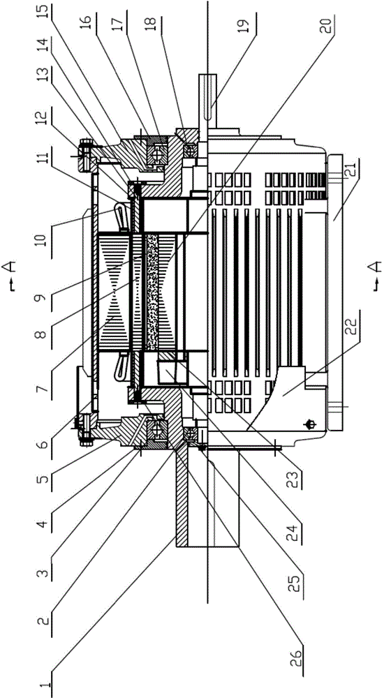
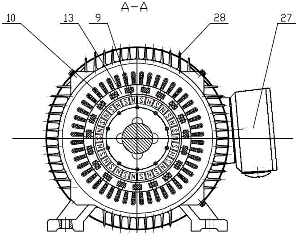
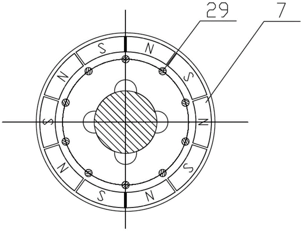
[0073] Such as Figure 1-7 As shown, a permanent magnet gear transmission device includes a stator assembly, a magnetic adjustment ring assembly, a rotor assembly and a casing assembly.

[0074] The stator assembly includes a stator core 7 and a stator winding 10; the stator core 7 is formed by laminating silicon steel sheets insulated on both sides, and the stator core 7 has slots with the same shape and uniform distribution; the stator winding 10 Embedded in the slot of the stator core 7, the stator winding 10 generates a rotating magnetic field when alternating current flows through it.

[0075] The stator core 7 and the casing 6 in the casing assembly are fixed by interference fit.

[0076] The stator core 7 is an outer stator core 7 or an inner stator core 7; when the stator core 7 is an outer stator core 7, the magnetic adjusting ring assembly and the rotor ass...


PUM


Abstract

The invention discloses a transmission mechanism for a permanent magnetic gear. The transmission mechanism comprises a stator assembly, an adjustable magnetic ring assembly, a rotor assembly and an enclosure assembly. The transmission mechanism is only provided with a layer of permanent magnet, so that the processing and assembling difficulty is smaller while a permanent magnet is saved. The permanent magnet is fixed by a built-in hole in a rotor core, and the condition that the permanent magnet is thrown away due to a centrifugal force generated by the rotor core during high-speed rotation is avoided, so that the permanent magnet is safe and reliable. The transmission ratio of the transmission mechanism can be changed according to the requirement; the output rotating speed of the transmission mechanism can be set to be constant according to the requirement. A damping bar made of a conductor material is arranged on the rotor core and can be used for cutting a magnetic field generated by a stator winding and forming induced current; a lorentz force generated by the induced current can form damping, so that the rotating speed and the torque of the rotor after starting are rapidly converged and the rotor stably operates; heat generated by the stator assembly, the adjustable magnetic ring assembly and the rotor assembly can be taken away by air current of the transmission mechanism.

Description

technical field [0001] The invention relates to a gear transmission device, in particular to a permanent magnet gear transmission device. Background technique [0002] As a power transmission device, the mechanical gear transmission device has a wide range of applications, covering almost every field of industrial and agricultural production and people's daily life. [0003] The introduction of mechanical gear transmission solves the problem of matching torque and speed in the transmission system. However, the introduction of mechanical gear transmission also brings problems such as vibration, noise, lubrication, reliability and regular maintenance to the transmission system. [0004] The permanent magnet gear transmission uses magnetic field coupling to transmit power, and has the characteristics of non-contact transmission, which avoids problems such as wear, noise, tooth pitting, and fracture caused by physical contact in traditional mechanical gear transmission, and red...

Claims


Application Information

Patent Timeline
Patent Type & Authority Applications(China)
IPC IPC(8): H02K51/00
Inventor 葛研军杨均悦王彪袁直王鹏周凯凯牛志
Owner DALIAN JIAOTONG UNIVERSITY
Why Eureka
Try Eureka