Automatic feeding system of fine blanking bar stock and using method thereof

An automatic feeding and strip material technology, which is applied to metal processing equipment, feeding devices, manufacturing tools, etc., can solve the problems of poor accuracy, high labor intensity, and low work efficiency, and achieve high accuracy and low labor intensity , high work efficiency

Active Publication Date: 2015-09-16
武汉欣天工精密机械有限公司
View PDF8 Cites 21 Cited by
  • Summary
  • Abstract
  • Description
  • Claims
  • Application Information

AI Technical Summary

Problems solved by technology

[0003] The purpose of the present invention is to overcome the defects and problems of high labor intensity, poor precision and low work efficiency in the prior art, and provide a working conditioner with low labor intensity, good precision and high work efficiency. Automatic material feeding system and using method thereof

Method used


Image

  • Automatic feeding system of fine blanking bar stock and using method thereof
  • Automatic feeding system of fine blanking bar stock and using method thereof
  • Automatic feeding system of fine blanking bar stock and using method thereof

Examples


Embodiment 1

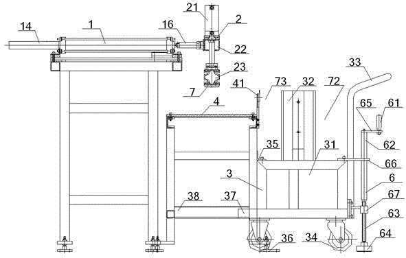
[0065] see figure 1 – image 3 , an automatic feeding system for fine blanking strips, the automatic feeding system includes a material moving device 1, a material lifting device 2 and a strip car 3, the material moving device 1 moves back and forth along a horizontal line, and the material lifting device 2 moves along a horizontal line The vertical line moves up and down, the output end of the material shifting device 1 is connected with the material lifting device 2, and a strip material 7 is placed in the strip car 3;

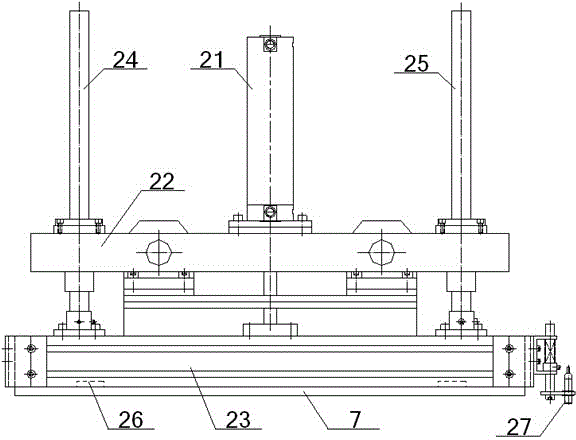
[0066] The material lifting device 2 includes a material lifting cylinder 21, a support plate 22 and a profile 23, the left side (i.e. the back side) of the support plate 22 is connected to the output end of the material moving device 1, and the center of the top of the support plate 22 is provided with Lifting material cylinder 21, the two ends of support plate 22 tops are provided with No. 1 material lifting slide bar 24, No. 2 lifting material sliding ba...

Embodiment 2

[0071] Basic content is the same as embodiment 1, the difference is:

[0072] see figure 1 , the outside of the armrest 33 is provided with a manual fixing device 6, the manual fixing device 6 includes a rotary handle 61, a rotary shaft 62, a rotary screw 63 and a fixing part 64, the bottom end of the rotary handle 61 is connected to the horizontal plate 65 and The top of the rotating shaft 62 is connected, the middle part of the rotating shaft 62 is connected with the top of the underbody frame 31 through the fixed plate 66, the bottom of the rotating shaft 62 is connected with the fixed part 64 after the rotating screw 63, and the rotating screw 63 The part near the bottom of the rotating shaft 62 is covered with a rotating bearing 67 that rotates with the rotating screw 63. The periphery of the rotating bearing 67 is connected with the bottom of the armrest 33; Braking device 36 is arranged, and one end away from armrest 33 on the bottom of the undercarriage frame 31 is co...

Embodiment 3

[0074] Basic content is the same as embodiment 1, the difference is:

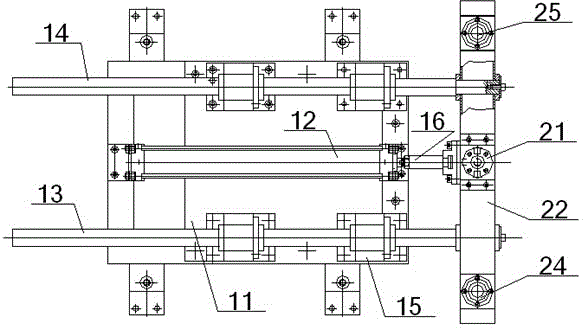
[0075] see figure 1 and figure 2 , the material shifting device 1 comprises a material shifting platform 11 and two parallel No. The front ends of the rod 13 and the No. 2 material-moving slide bar 14 respectively pass through the bearing housing 15 and are connected to the back of the support plate 22, and the middle part of the back of the support plate 22 is connected to the output end of the material-moving cylinder 12 through the connecting shaft 16, and The material transfer cylinder 12 is located between the No. 1 material transfer slide bar 13 and the No. 2 material transfer slide bar 14 .

[0076] When in use, the output end of the material transfer cylinder 12 drives the support plate 22 to do horizontal reciprocating motion through the connecting shaft 16. At the same time, the No. The support plate 22 is driven.


PUM


Abstract

An automatic feeding system of a fine blanking bar stock comprises a material shifting device, a material lifting device and a bar stock trolley, the material shifting device drives the material lifting device to carry out horizontal back and forth movement, sectional materials in the material lifting device are driven to move up and down through a lifting cylinder, electromagnets are arranged on the sectional materials, and a bar stock is arranged in a bar stock groove in the bar stock trolley. When the automatic feeding system is used, the material shifting device first drives the sectional materials to move to the position over the bar stock groove, the material lifting cylinder drives the sectional materials to move downwards to attract the bar stock through the electromagnets and then moves upwards, and the material shifting device drives the sectional materials to return to place the attracted bar stock on a blanking platform. The automatic feeding system of the fine blanking bar stock is small in labor intensity, good in accuracy and high in working efficiency, it can be guaranteed that only one bar stock is attracted every time, and the bar stock can be fixed effectively.

Description

technical field [0001] The invention relates to a feeding device for strips, in particular to an automatic feeding system for fine blanking strips and a method for using the same, which is particularly suitable for reducing labor intensity, improving the accuracy of feeding, and has high work efficiency. Background technique [0002] Strip refers to a long metal slab, which can be magnetically attracted, and this kind of slab is used as a raw material for fine blanking. Generally speaking, in the process of processing the strips, frequent material removal is required to periodically place the strips on the processing platform. The traditional manual operation is not only labor-intensive, but also low in efficiency. Contents of the invention [0003] The purpose of the present invention is to overcome the defects and problems of high labor intensity, poor precision and low work efficiency in the prior art, and provide a working conditioner with low labor intensity, good pre...

Claims


Application Information

Patent Timeline
Patent Type & Authority Applications(China)
IPC IPC(8): B21D43/02B21D43/18
CPCB21D43/026B21D43/04B21D43/18
Inventor 宋志峰章毅胡继文陈燚涛李刚毅周娣
Owner 武汉欣天工精密机械有限公司
Why Eureka
Try Eureka