Large-diameter thin walled cylinder butt welding assembly clamping device

A thin-walled cylinder, welding assembly technology, applied in welding equipment, non-electric welding equipment, metal processing equipment, etc., can solve the problems of difficult loading and unloading adjustment, low reliability, low work efficiency, etc., and achieve simple and easy assembly and adjustment, accurate fixation and positioning, to ensure the effect of welding quality

Active Publication Date: 2015-09-16
CENT SOUTH UNIV
View PDF8 Cites 6 Cited by
  • Summary
  • Abstract
  • Description
  • Claims
  • Application Information

AI Technical Summary

Problems solved by technology

At present, friction stir welding is the preferred welding process for the welding of the rocket launcher section and the tank, but the premise of achieving stable welding is the precise positioning and reliable clamping of the two sections of the cylinder, so as to avoid the workpiece caused by force and high temperature cycle during welding. Welding deformation, which requires huge, complicated and clumsy inner support tooling, and the workpiece is usually a flexible thin-walled semi-closed component, especially for cylinders and tanks that require multi-section butt welding assembly, the inner support tooling has a complex structure and is subject to Restrictions between the inside of the cylinder and the hole, difficulty in loading and unloading adjustment, poor process flexibility, low reliability, low work efficiency, long cycle and other problems, it is difficult to meet the needs of the rapid development of aerospace technology

Method used


Image

  • Large-diameter thin walled cylinder butt welding assembly clamping device
  • Large-diameter thin walled cylinder butt welding assembly clamping device
  • Large-diameter thin walled cylinder butt welding assembly clamping device

Examples


Embodiment Construction

[0016] Below in conjunction with accompanying drawing and embodiment the patent of the present invention is further described.

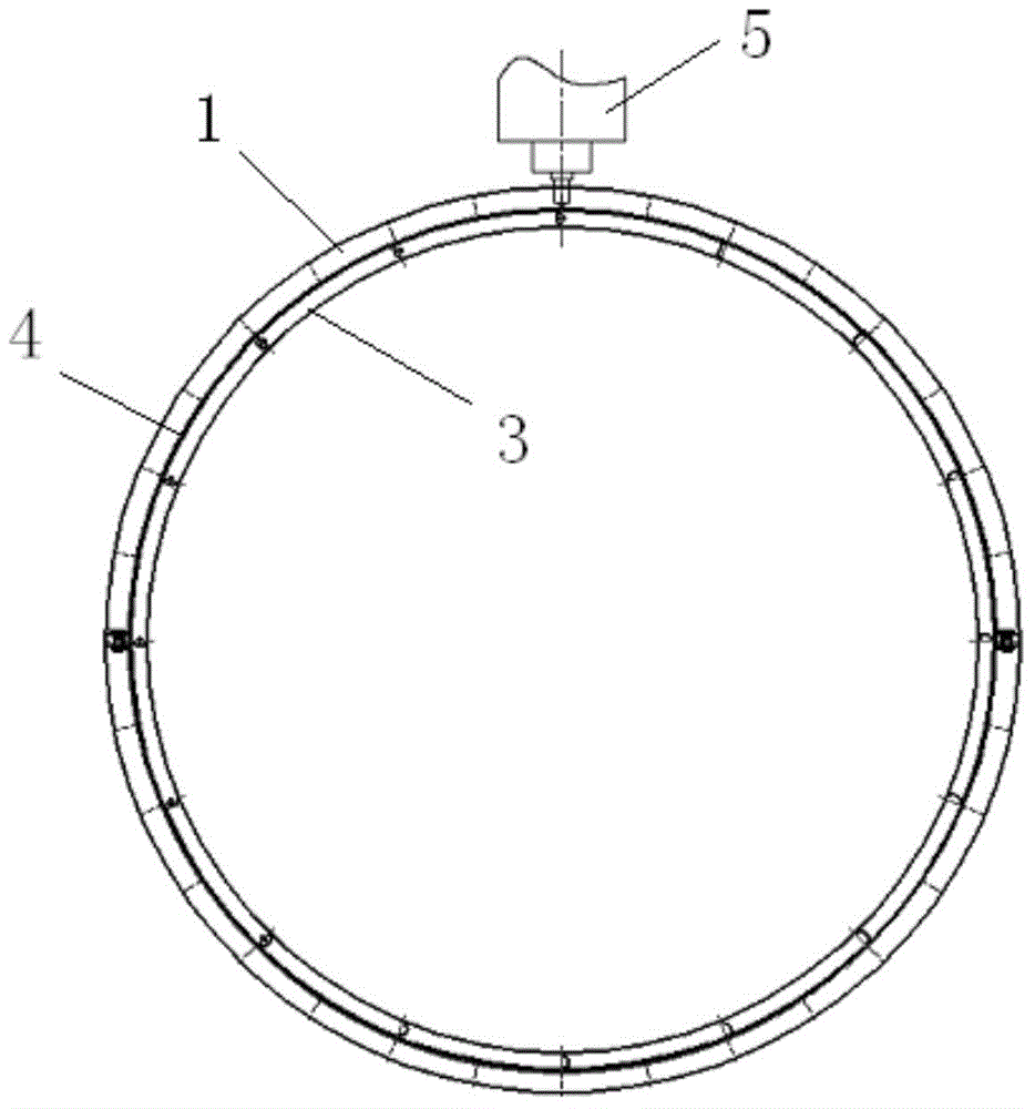
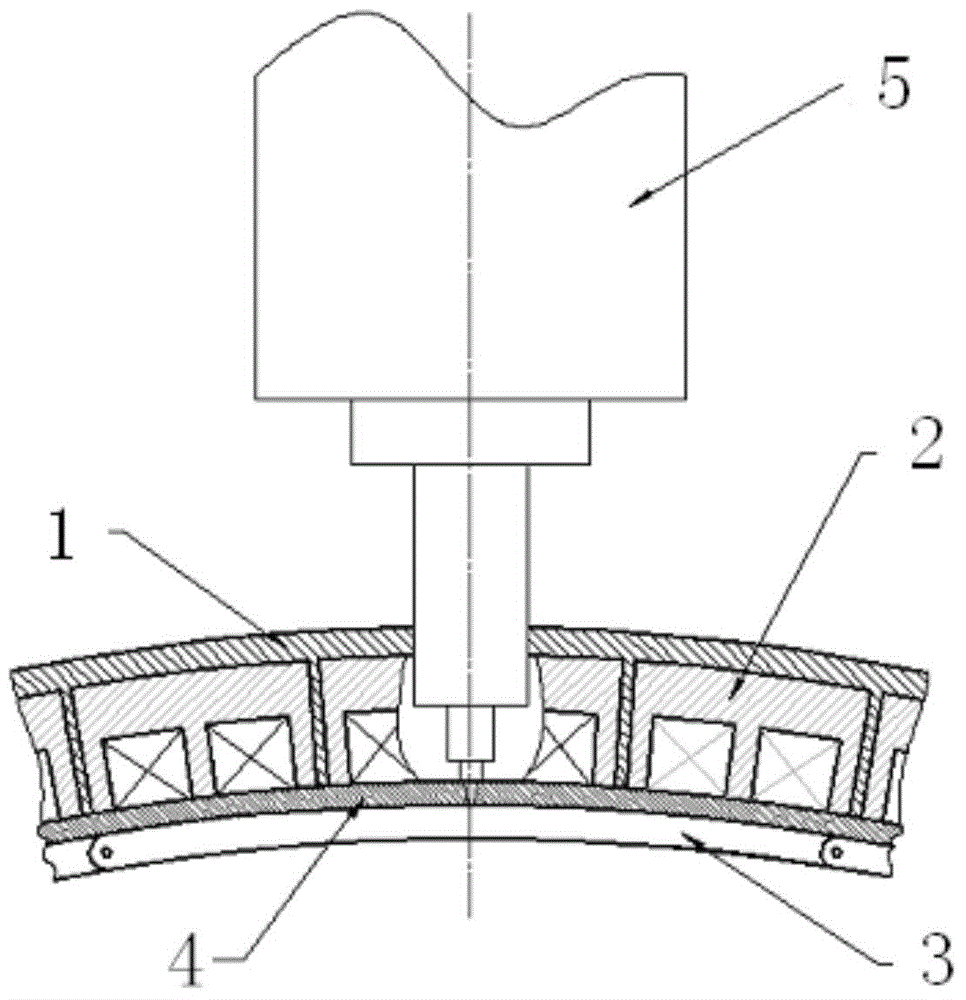
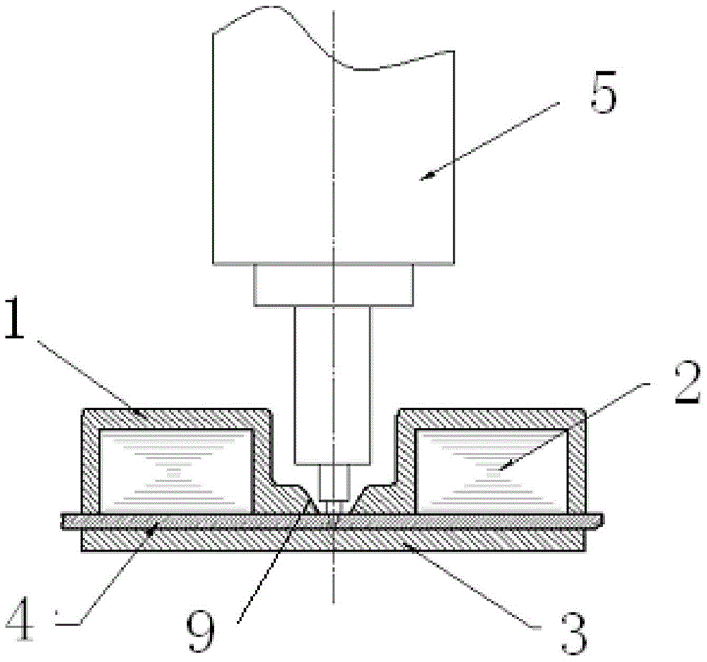
[0017] see figure 1 , figure 2 , image 3 and Figure 4 , large-diameter thin-wall cylinder butt welding assembly clamping device, including two sets of rigid outer ring 1 and a combined inner pad 3, the inner diameter of each set of rigid outer ring 1 matches the outer diameter of large-diameter thin-wall cylinder 4, and each set of rigid The outer ring 1 is composed of at least two sets of rigid semi-outer rings connected by bolts 6, and one side of each set of rigid outer rings 1 is provided with a slope 9, and the slope 9 of the two sets of rigid outer rings 1 is along two sides of the weld seam of the large-diameter thin-walled cylinder 4. The side is relatively continuous distribution, the electromagnet 2 is fixed in the rigid outer ring 1 along both sides of the weld, and the combined inner pad 3 is composed of several sections of arc plat...


PUM


Abstract

The invention discloses a large-diameter thin walled cylinder butt welding assembly clamping device. The large-diameter thin walled cylinder butt welding assembly clamping device comprises two sets of rigid outer rings (1) and a combined type inner pad (3), the inner diameter of each set of rigid outer ring (1) is matched with the outer diameter of a large-diameter thin walled cylinder, each set of rigid outer rings (1) is formed by the connection of the at least two sets of rigid outer rings (1) through bolts (6), a slope (9) is arranged at one side of each set of rigid outer rings (1), electromagnets (2) are fixed into the rigid outer rings (1) along the two sides of a welding seam, and the combined type inner pad (3) is formed by the head-tail sequential connection of a plurality of sections of arc-shaped plates (7) through pin holes formed in the two ends of each arc-shaped plate (7) and fixing pins (8) arranged in the pin holes. According to the large-diameter thin walled cylinder butt welding assembly clamping device, when the large-diameter thin walled cylinder stirring friction butt welding installation especially the semi-closed cylinder annular welding installation is performed, complex inner supporting tools are not needed, the assembly and the disassembly of the inner supporting tools are simplified, the fixation and the location on the butt joint position of a thin walled cylinder can be performed lightly and handily and accurately, the assembly and the adjustment are simple and practicable, meanwhile, the assembly precision of large-scale cylinders is improved, and the welding quality is guaranteed.

Description

technical field [0001] The patent of the present invention relates to a device for assembling and locating a large aluminum alloy thin-walled cylinder with magnetic inner support friction stir welding, especially a fixing and positioning device for butt welding assembly of such a cylinder. Background technique [0002] In the field of aerospace industry, large-scale aluminum alloy thin-walled cylindrical components are widely used in large rocket launcher sections and tanks. These components are generally assembled by butt welding of several sections of cylinders to achieve high-quality, high reliability and high-efficiency welding. Packaging is one of the key technologies that the industry needs to break through. At present, friction stir welding is the preferred welding process for the welding of the rocket launcher section and the tank, but the premise of achieving stable welding is the precise positioning and reliable clamping of the two sections of the cylinder, so as t...

Claims


Application Information

Patent Timeline
Patent Type & Authority Applications(China)
IPC IPC(8): B23K20/12
CPCB23K20/126
Inventor 贺地求
Owner CENT SOUTH UNIV
Why Eureka
Try Eureka