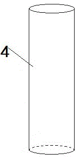
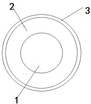
A buffer column for road
A technology of buffer columns and roads, which is applied in the direction of roads, roads, road safety devices, etc., can solve the problems of low safety, high cost, short life, etc., achieve good impact energy absorption, good impact resistance, and reduce product quality. Effect
- Summary
- Abstract
- Description
- Claims
- Application Information
AI Technical Summary
Problems solved by technology
Method used
Image
Examples
Embodiment 1
[0041] A buffer column for roads, the buffer column is cylindrical, the core of the buffer column is a particle-reinforced foamed aluminum-based composite material, the core is wrapped with an elastic material layer, and the elastic material layer is a titanium alloy cylinder, which is characterized in that:
[0042] The particle-reinforced foamed aluminum-based composite material is prepared by the following preparation method:
[0043] Prepare an aluminum alloy ingot, its composition percentage is: Cr 3%, Ni 1%, Mo 0.7%, Mg 0.1%, Zn 0.1%, Fe 0.07%, Ce 0.03%, Nb 0.01%, and the balance is Al;
[0044] Melt the above-mentioned aluminum alloy and raise the temperature to 700°C-760°C, pass through protective Ar gas to refine and keep it warm for 10 minutes;
[0045] Add thickener accounting for 6-7% of the total weight of the melt and add silicon carbide and / or alumina particles accounting for 10-12% of the mass fraction of the melt, stir the molten metal at a speed of 500-800rpm...
Embodiment 2
[0053] A buffer column for roads, the buffer column is cylindrical, the core of the buffer column is a particle-reinforced foamed aluminum-based composite material, the core is wrapped with an elastic material layer, and the elastic material layer is a titanium alloy cylinder, which is characterized in that:
[0054] The particle-reinforced foamed aluminum-based composite material is prepared by the following preparation method:
[0055] Prepare an aluminum alloy ingot, its composition percentage is: Cr 4%, Ni 2%, Mo 0.8%, Mg 0.2%, Zn 0.2%, Fe 0.08%, Ce 0.04%, Nb 0.02%, and the balance is Al;
[0056] Melt the above-mentioned aluminum alloy and raise the temperature to 700°C-760°C, pass through protective Ar gas to refine and keep it warm for 10 minutes;
[0057] Add thickener accounting for 6-7% of the total weight of the melt and add silicon carbide and / or alumina particles accounting for 10-12% of the mass fraction of the melt, stir the molten metal at a speed of 500-800rpm...
Embodiment 3
[0065] A buffer column for roads, the buffer column is cylindrical, the core of the buffer column is a particle-reinforced foamed aluminum-based composite material, the core is wrapped with an elastic material layer, and the elastic material layer is a titanium alloy cylinder, which is characterized in that:
[0066] The particle-reinforced foamed aluminum-based composite material is prepared by the following preparation method:
[0067] Prepare an aluminum alloy ingot, its composition percentage is: Cr 3.5%, Ni 1.5%, Mo 0.75%, Mg 0.15%, Zn 0.15%, Fe 0.075%, Ce 0.035%, Nb 0.015%, and the balance is Al;
[0068] Melt the above-mentioned aluminum alloy and raise the temperature to 700°C-760°C, pass through protective Ar gas to refine and keep it warm for 10 minutes;
[0069] Add thickener accounting for 6-7% of the total weight of the melt and add silicon carbide and / or alumina particles accounting for 10-12% of the mass fraction of the melt, stir the molten metal at a speed of ...
PUM
| Property | Measurement | Unit |
|---|---|---|
| particle diameter | aaaaa | aaaaa |
Abstract
Description
Claims
Application Information
 - R&D
- Intellectual Property
- Life Sciences
- Materials
- Tech Scout
- Unparalleled Data Quality
- Higher Quality Content
- 60% Fewer Hallucinations
Browse by: Latest US Patents, China's latest patents, Technical Efficacy Thesaurus, Application Domain, Technology Topic, Popular Technical Reports.
© 2025 PatSnap. All rights reserved.Legal|Privacy policy|Modern Slavery Act Transparency Statement|Sitemap|About US| Contact US: help@patsnap.com


