Deposition-evaporation system and deposition-evaporation transmission device

A technology of evaporation system and transmission device, which is applied in the field of deposition evaporation system, can solve the problems of limited evaporation, high cost, and low production capacity, and achieve the effects of improving uniformity, increasing production capacity, and reducing production costs

Active Publication Date: 2015-09-16
HANGZHOU SILAN INTEGRATED CIRCUIT
View PDF7 Cites 7 Cited by
  • Summary
  • Abstract
  • Description
  • Claims
  • Application Information

AI Technical Summary

Problems solved by technology

[0003] At present, the applied oblique angle deposition evaporation system needs to adopt two motors to control the substrate ( Image 6 There is no revolution in the center) rotation and tilt angle, and the motors are located inside the vacuum chamber, such as Image 6 As shown, the evaporation system of this structure adopts two motors 002 and 003 inside the cavity 001, which are used to control the tilt angle and rotation speed of the substrate 004 respectively. Restriction, the substrate must be fixed, and the use of motors to control the tilt angle can only place one substrate for deposition. Since one motor can only control the tilt angle or rotation of one substrate, if multiple pieces are required to be deposited at the same time, it is necessary to add a motor The number of substrates is controlled separately, which increases the cost of evaporation equipment and its maintenance
In addition, the operating temperature of the motor is generally lower than 135°C, which also limits the evaporation under high temperature conditions
Its production capacity is relatively low and its cost is high, so it is not suitable for large-scale industrial production.

Method used


Image

  • Deposition-evaporation system and deposition-evaporation transmission device
  • Deposition-evaporation system and deposition-evaporation transmission device
  • Deposition-evaporation system and deposition-evaporation transmission device

Examples


Embodiment Construction

[0048]Various embodiments of the invention will be described in more detail below with reference to the accompanying drawings. In the various drawings, the same elements are denoted by the same or similar reference numerals. For the sake of clarity, various parts in the drawings have not been drawn to scale.

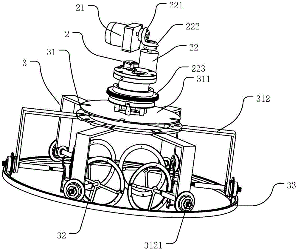
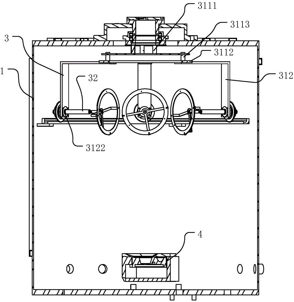
[0049] Such as Figure 1-2 As shown, the oblique angle deposition evaporation system in this application includes a vacuum chamber shell 1 , a power mechanism 2 , a deposition evaporation transmission device 3 and a vacuum evaporator 4 . A part of the power mechanism 2 is located outside the vacuum chamber housing 1, the deposition evaporation transmission device 3 and the vacuum evaporator 4 are located inside the housing, and the power mechanism 2 is in phase with the deposition evaporation transmission device 3 connected to drive the deposition and evaporation transmission device 3 to rotate. The vacuum evaporator 4 can be thermal evaporation or electron beam evapo...


PUM


Abstract

The invention relates to a deposition-evaporation system and a deposition-evaporation transmission device. The deposition-evaporation system is used for performing inclined evaporation-deposition on substrates and comprises a power mechanism, a deposition-evaporation transmission device and a vacuum evaporator, wherein the power mechanism is connected with the deposition-evaporation transmission device and is used for driving the deposition-evaporation transmission device to rotate; the vacuum evaporator is positioned below the deposition-evaporation transmission device; the evaporation source of the vacuum evaporator is arranged opposite to deposition-evaporation transmission device; and the longitudinal center line of the evaporation source is parallel with the plane of the substrate. The deposition-evaporation system provided by the invention has the advantages that a plurality of substrates can be evaporated, the rotating speed of each substrate can be adjusted, and the inclined angle of each substrate can be adjusted, is beneficial for increasing productivity and reducing production cost, and is applicable to batch production of inclined angle evaporation nanostructure films.

Description

technical field [0001] The invention relates to the technical field of a deposition evaporation system, in particular to an oblique angle deposition evaporation system and an oblique angle deposition evaporation transmission device. Background technique [0002] The oblique-angle deposition technique is a novel and effective thin-film preparation method that combines traditional thin-film vacuum deposition with controllable substrate rotation. In the traditional thin film deposition technology, the particle beam is incident on the substrate surface along the normal direction of the substrate (ie normal incidence deposition). The oblique angle deposition technology is to tilt the substrate (or change the incident direction of the particle beam), so that the incident direction of the particle beam and the normal line of the substrate surface form a certain angle (ie, the deposition angle). Has a slanted columnar structure. By changing the inclination angle and rotation speed...

Claims


Application Information

Patent Timeline
Patent Type & Authority Applications(China)
IPC IPC(8): C23C14/24C23C14/50
Inventor 乐仲孙福河闻永祥曹永辉
Owner HANGZHOU SILAN INTEGRATED CIRCUIT
Why Eureka
Try Eureka