Eureka AIR delivers breakthrough ideas for toughest innovation challenges, trusted by R&D personnel around the world.

Chemical vapor deposition apparatus

A technology of chemical vapor deposition and gas shower head, which is applied in the direction of gaseous chemical plating, metal material coating process, coating, etc., can solve the problems of substrate tray damage, increase of heater cost, radiation heat loss, etc., and achieve Reduce power and temperature requirements, prolong service life, and reduce radiation loss

Active Publication Date: 2015-09-16
ADVANCED MICRO FAB EQUIP INC CHINA
View PDF10 Cites 7 Cited by
  • Summary
  • Abstract
  • Description
  • Claims
  • Application Information

AI Technical Summary

Problems solved by technology

In the above-mentioned reaction chamber, the edge of the substrate tray is close to the side wall of the reaction chamber. The substrate tray usually works in an environment of 500-1500 degrees Celsius. Since the side wall of the reaction chamber is equipped with a cooling liquid channel, the temperature is much lower. Due to the working temperature of the substrate tray, the temperature difference between the substrate tray and the side wall of the reaction chamber is relatively large, resulting in serious radiation heat loss at the edge of the substrate tray and affecting the temperature uniformity of the substrate tray
In order to ensure that the temperature of the substrate tray is uniform, the heater in the area below the edge of the substrate tray must maintain a high temperature and high power state for a long time, so as to compensate for the influence of the side wall of the reaction chamber with the cooling liquid channel on the temperature of the edge of the substrate tray. Therefore, the material and life requirements of the heater below the edge of the substrate tray are relatively special, which increases the cost of the heater
In addition, during the heating or cooling process, if the temperature of the heater below the edge of the substrate tray is not properly controlled, the temperature difference between the edge and center of the substrate tray will be too large, which may cause damage to the substrate tray

Method used


Image

  • Chemical vapor deposition apparatus
  • Chemical vapor deposition apparatus
  • Chemical vapor deposition apparatus

Examples


Embodiment Construction

[0023] The present invention discloses a chemical vapor deposition device. In order to make the above objects, features and advantages of the present invention more obvious and easy to understand, the specific implementation of the present invention will be described in detail below in conjunction with the accompanying drawings and examples.

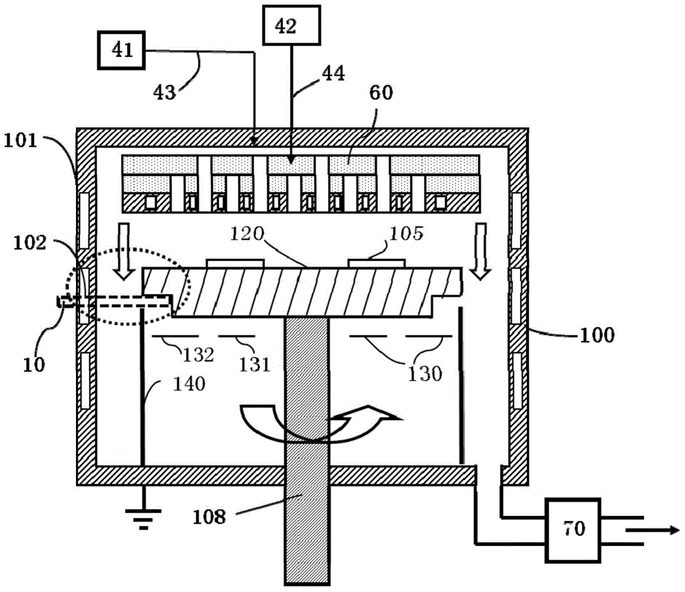
[0024] figure 1 A schematic structural view of the chemical vapor deposition device of the present invention is shown, the device includes a reaction chamber 100, the reaction chamber 100 includes a reaction chamber side wall 101 surrounding the reaction chamber 100, and the reaction chamber 100 also includes a rotating shaft 108, which is placed A substrate tray 120 with a plurality of substrates 105 is mounted on the top of the rotating shaft 108 , and a heater 130 is located below the substrate tray 120 and is arranged around the rotating shaft 108 . The top of the reaction chamber 100 includes a gas shower head 60 for uniformly distr...


PUM


Abstract

The invention discloses a chemical vapor deposition apparatus. The chemical vapor deposition apparatus comprises a reaction chamber, the top of the reaction chamber is provided with a gas spray head, a substrate pallet supported through a rotating shaft is arranged below the gas spray head, the substrate pallet is arranged to be a main body pallet and an edge ring encircling the main body pallet, and the heat insulating and shielding effects of the edge ring are used to reduce the radiation loss of the heat of the main body pallet to the sidewall of the reaction chamber, reduce requirements on the power and temperature of a heater of the edge area, prolong the service life of the heater and effectively maintain the uniformity of the temperature of the substrate pallet.

Description

technical field [0001] The present invention relates to the manufacture of semiconductor devices, in particular to a device for growing epitaxial layers or performing chemical vapor deposition on substrates such as substrates. Background technique [0002] Chemical vapor deposition (CVD) reactors, especially metal-organic chemical vapor deposition (MOCVD) reactors are the main equipment for the production of optical devices such as light-emitting diode (LED) epitaxial chips. Typical chemical vapor deposition (CVD) and metal-organic chemical vapor deposition (MOCVD) reactors both require rotating the carrier plate on which the processed substrate is placed during deposition to provide a uniform deposition effect on the substrate. A typical vapor deposition reactor structure is a reaction chamber surrounded by side walls of the reaction chamber. The reaction chamber includes a rotating shaft, and a substrate tray on which several substrates are placed is installed on the top o...

Claims


Application Information

Patent Timeline
Patent Type & Authority Applications(China)
IPC IPC(8): C23C16/458
Inventor 杜志游姜勇
Owner ADVANCED MICRO FAB EQUIP INC CHINA
Why Eureka
Eureka Blog
Learn More