
Box and truss composite node structure of steel box and truss composite bridge

A steel box and steel truss technology, applied in bridges, buildings, etc., can solve problems such as inconvenience in construction and difficult construction and welding, and achieve the effect of saving material consumption, facilitating later maintenance and convenient construction

Inactive Publication Date: 2015-09-16
CHINA MAJOR BRIDGE ENERGINEERING
View PDF6 Cites 5 Cited by
  • Summary
  • Abstract
  • Description
  • Claims
  • Application Information

AI Technical Summary

Problems solved by technology

The mechanical characteristics of traditional steel truss bridges require the rods to be as small as possible, resulting in a smaller cross-section of the rods and thicker steel plates, and for stay cables or suspension cables anchored at the upper chord nodes, due to the limitation of the size of the rods, the construction It is very inconvenient, and this part is the most critical force, the small cross-section and thick steel plate lead to difficulties in construction welding

Method used


Image

  • Box and truss composite node structure of steel box and truss composite bridge
  • Box and truss composite node structure of steel box and truss composite bridge
  • Box and truss composite node structure of steel box and truss composite bridge

Examples


Embodiment Construction

[0014] The present invention will be described in detail below with reference to the accompanying drawings.

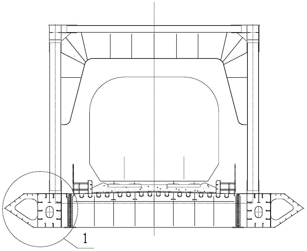
[0015] refer to figure 1 , the present invention 1 is arranged at the box truss joint of the steel box steel truss combined girder bridge, so that most of the force of the steel box steel truss combined girder bridge box truss joint can be concentrated on the steel box with a larger lower chord section.

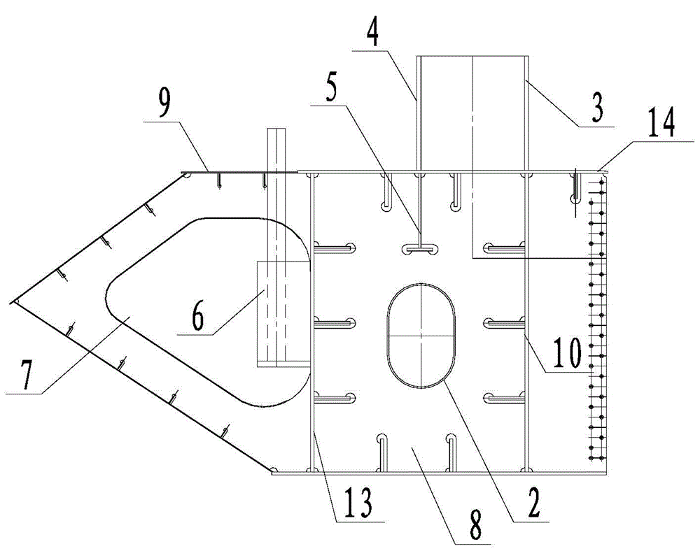
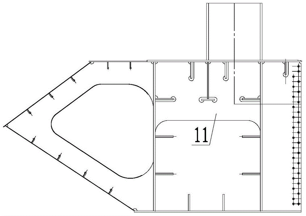
[0016] refer to Figure 2-5 , the top plate 14 of the steel box is provided with the web bar inner connecting plate 3 and the web bar outer connecting plate 4, and the web bar inner connecting plate 3 is aligned with the steel box inner web plate 10 for alignment welding, and the web bar outer connecting plate 4 is connected with the web bar outer side The inverted T-shaped ribs 5 of the connecting plate are aligned and welded, and the width of the bar can be flexibly determined according to the force of the upper chord and the web, instead of being the same width as...


PUM


Abstract

The invention relates to a box and truss composite node structure of a steel box and truss composite bridge. A web member inside connecting plate and a web member outside connecting plate are arranged on a top plate of a steel box; the web member inside connecting plate is aligned to and welded with a steel box inner web plate; and an inverted T-shaped rib of the web member outside connecting plate is aligned to and welded with the web member outside connecting plate. A tuyere is arranged on the outer side of the steel box. A plurality of partitions are arranged in the steel box at a node to enhance the rigidity of the node and improve the stressed state of the node. The steel box is internally provided with whole partitions and semi-partitions; manholes are formed in the whole partitions; and a steel anchor box is arranged in the tuyere to facilitate later maintenance. A man hole is formed in a top plate of the tuyere for later overhaul and maintenance of the node. The steel anchor box of a stay cable of a cable-stayed bridge or a suspension cable of a suspension bridge is arranged in the tuyere and welded on a steel box outside web plate. The structure is convenient to construct and definite and reasonable in stress, transfers a force directly, reduces material usage, can ensure construction quality, facilitates later maintenance, and is applicable to a beam bridge, a cable-stayed bridge and a suspension bridge. The Dongting Lake grand bridge as a railway coal transportation corridor from the west Inner Mongolia to the central China employs the structure, and the application effect is good.

Description

technical field [0001] The invention relates to a box-truss joint structure of a steel box and steel truss combined girder bridge. Background technique [0002] The steel box and steel truss joint is the key structure connecting the truss web and the steel box. The mechanical characteristics of traditional steel truss bridges require the rods to be as small as possible, resulting in a smaller cross-section of the rods and thicker steel plates, and for stay cables or suspension cables anchored at the upper chord nodes, due to the limitation of the size of the rods, the construction It is very inconvenient, and this part is the most critical force, the small cross-section and thick steel plate lead to the difficulty of construction welding. [0003] The steel box and steel truss combined girder bridge has a large cross-section, thin plates, and a large internal space. The steel box is the main force-bearing member, and the truss web and upper chord play a role in strengthenin...

Claims


Application Information

Patent Timeline
IPC IPC(8): E01D12/00
Inventor 易伦雄肖海珠王东晖康晋张晓勇赵兴亚孙立山
Owner CHINA MAJOR BRIDGE ENERGINEERING
Learn More