
Yacht engine cabin vibration absorber

A technology for engine rooms and yachts, applied in the field of yachts, can solve the problems of deformation, tearing or aging, falling to the ground, reducing the use function and life, and achieving the effect of convenient use and simple structure

Inactive Publication Date: 2015-09-16
YAGUANG TECH GRP CO LTD
View PDF4 Cites 4 Cited by
  • Summary
  • Abstract
  • Description
  • Claims
  • Application Information

AI Technical Summary

Problems solved by technology

[0003] Existing yacht shock absorbers mainly adopt the basic structural principle of mass inertia block + rubber body + mounting bracket, and rarely consider the appropriate limit setting. However, since the shock absorber is often installed at the position with the largest amplitude, the actual During use, especially in occasions with large vibration amplitude, such as yacht engine room power system, under the long-term inertia of the mass inertia block, the vibration-absorbing rubber is prone to ultra-limit deformation, tearing or aging, reducing the use function and life. Under extreme conditions, The mass inertial block comes out unconstrained and damages the mounting bracket and peripheral components, and even falls to the ground or is knocked out by rotating components, which poses a safety hazard, which limits the further expansion of the application and promotion of products with similar structures

Method used


Image

  • Yacht engine cabin vibration absorber

Examples


specific Embodiment approach

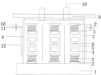
[0009] detailed description: Reference attached figure 1 , including a base 1, a shock absorbing port 2, a spring 3, a first baffle 8, and a second baffle 7, wherein the first baffle 8 and the second baffle 7 form a lateral space limiting space and are vertically and fixedly connected to the support plate 9, At least a part of the first baffle plate 8 and the second stop block 7 are inserted into the lateral space to limit the lateral displacement of the support plate 9, and the two ends of the first baffle plate 8 and the second block 7 are connected to the first baffle plate 8 by self-tapping bolts. A buffer plate 11 and a second buffer plate 12 are respectively fixedly connected, the middle of the shock absorber is the piston 3, the upper and lower ends of the piston 6 are provided with springs 3, and the ring at the bottom of the spring 3 is connected with the piston 6 through the sharp part, and the inside of the piston 6 Two disc magnets 4 are set.

[0010] Further, ...


PUM


Abstract

A yacht engine cabin vibration absorber structure is characterized in that the yacht engine cabin damper comprises a base (1), a vibration absorbing port (2), a spring (3), a first baffle plate (8) and a second baffle plate (7), wherein the first baffle plate (8) and the second baffle plate (7) are used to formed a horizontal limitation space and the first baffle plate (8) and the second baffle plate (7) are fixingly connected to a supporting plate (9) in a vertical way; at least a part of the first baffle plate (8) and the second baffle plate (7) is inserted into the horizontal limitation space for defining the horizontal displacement of the supporting plate (9); two ends of the first baffle plate (8) and the second baffle plate (7) are respectively fixingly connected to a first buffer plate (11) and a second buffer plate (12) through a self-tapping bolt; a piston (3) is set in the middle of the a damper; upper and lower ends of a piston (6) are provided with springs (3); a round ring on the bottom end of the spring (3) are connected to the piston (6) through a stab portion; and two round magnetic bodies (4) are set inside the piston (6). According to the invention, the vibration isolation effect is realized when a vibration component regularly runs; and the horizontal displacement of the vibration component is ensured to not occur when an earthquake occurs or strong impact is applied, thus the vibration component and the surrounding components and apparatus are ensured not to be damaged.

Description

technical field [0001] The invention relates to the technical field of yachts, in particular to a yacht engine room shock absorber structure. Background technique [0002] Yachts will inevitably bump when driving on the water, causing vibrations to the engine room. In order to slow down this vibration, shock absorbers are generally installed in parallel with the power of the engine room. [0003] Existing yacht shock absorbers mainly adopt the basic structural principle of mass inertia block + rubber body + mounting bracket, and rarely consider the appropriate limit setting. However, since the shock absorber is often installed at the position with the largest amplitude, the actual During use, especially in occasions with large vibration amplitude, such as yacht engine room power system, under the long-term inertia of the mass inertia block, the vibration-absorbing rubber is prone to ultra-limit deformation, tearing or aging, reducing the use function and life. Under extreme ...

Claims


Application Information

Patent Timeline
IPC IPC(8): F16F15/023F16F15/03F16F15/04B63B3/56
CPCF16F15/03B63B3/56F16F15/08
Inventor 杜汝珊鲁朝军周超
Owner YAGUANG TECH GRP CO LTD
Learn More