Reaction container

A reaction vessel and accommodating space technology, which is applied in the field of application vessels, can solve the problems of poor stirring effect and low utilization rate of steam in the reaction vessel, and achieve the effects of improving the stirring effect, improving the utilization rate, and improving the stirring effect

Active Publication Date: 2015-09-23
ZHEJIANG TIANCHEN PLASTIC IND
View PDF6 Cites 9 Cited by
  • Summary
  • Abstract
  • Description
  • Claims
  • Application Information

AI Technical Summary

Problems solved by technology

[0004] Therefore, the technical problem to be solved by the present invention lies in the problems of poor stirring effect, low steam utilization rate and noise generation in the prior art reaction vessel, thereby providing a reaction vessel with good stirring effect, high steam utilization rate and no noise pollution

Method used


Image

  • Reaction container
  • Reaction container
  • Reaction container

Examples


Embodiment 1

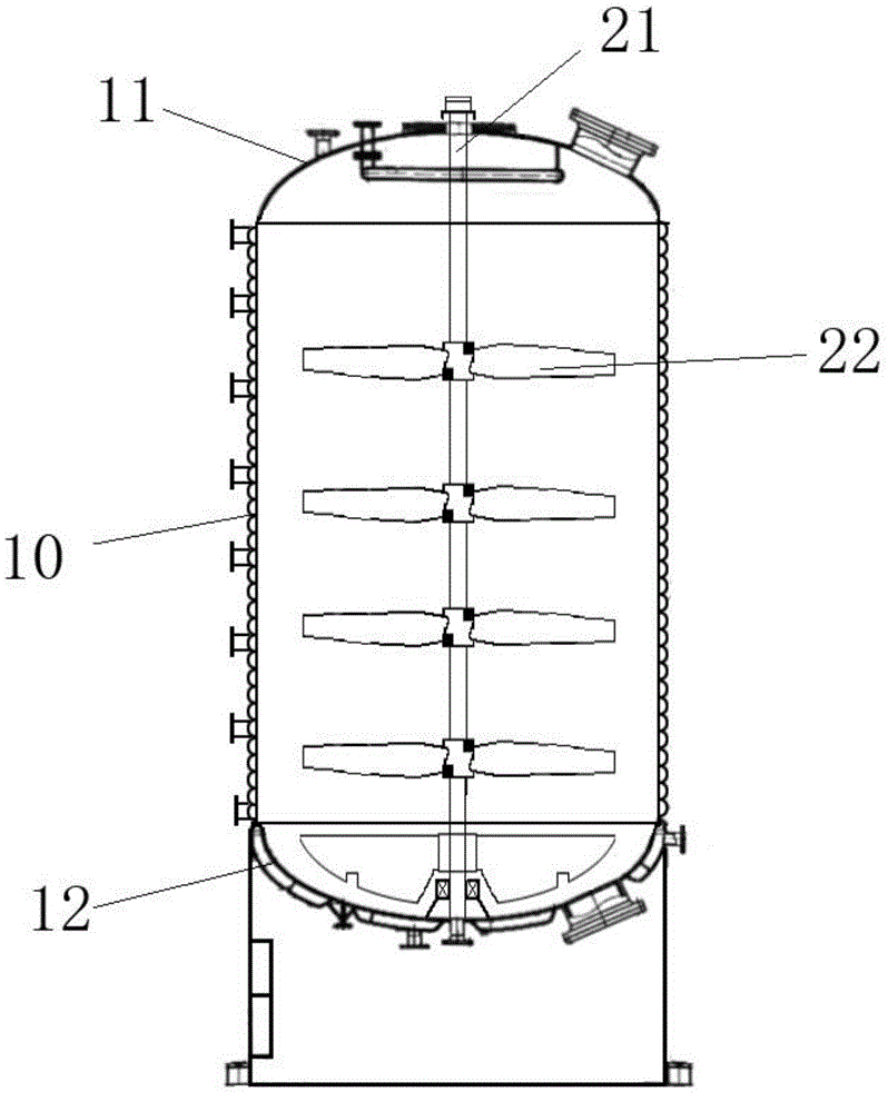
[0042] This embodiment provides a kind of reaction container, is adapted to as the reaction container that needs soft water as reaction raw material and needs to heat up, as figure 1 and 3 and 4, including,

[0043] The tank body 10 has an accommodation space;

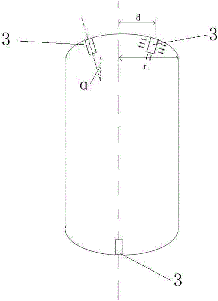
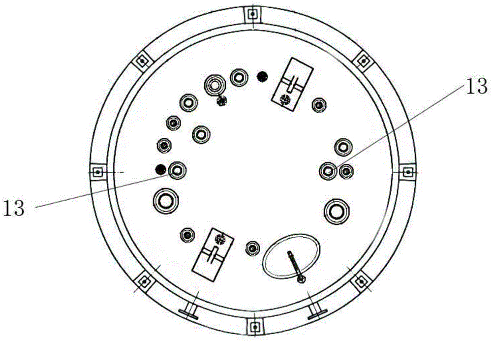
[0044] Steam inlets 13, preferably 4, 2 are arranged on the tank top 11 at the top of the tank body 10, and 2 are arranged on the tank bottom 12 at the bottom of the tank body 10, as figure 2 As shown, it is worth noting that, figure 2 The two steam inlets 13 on the bottom 12 of the middle tank overlap. In the top view of the tank body 10, the line connecting the two steam inlets 13 on the top 11 of the tank and the two steam inlets 13 on the bottom 12 of the tank perpendicular to each other;

[0045] The steam dispersing element 3 is located in the accommodating space, and is used to introduce the steam from the steam inlet 13 into the accommodating space, having

[0046] The inner cylinder 31 forms a steam intro...

Embodiment 2

[0069] This embodiment provides a reaction vessel, which is a modification based on Example 1. The difference between this embodiment and Example 1 is that the reaction vessel of this embodiment,

[0070] The sum of the areas of all the second through holes 323 is S1, the sum of the areas of all the first through holes 313 is S2, the cross-sectional area of ​​the opening is S3, and S1, S2, and S3 conform to the following proportional relationship:

[0071] S1:S2:S3=8:1:4.

[0072] The ratio of the diameter of the steam introduction chamber 4 to the diameter of the steam buffer chamber is R4:R5=1.8:1, the width of the gap is D, the length of the steam buffer chamber is L, and D and L satisfy the following proportional relationship D:L=1:7.

[0073] The diameter of the second through hole 323 is R1, the diameter of the first through hole 313 is R2, the diameter of the opening 41 is R3, R1, R2, R3 satisfy the following proportional relationship: R1: R2: R3 =1:4:5.

[0074] The...

Embodiment 3

[0078] This embodiment provides a reaction container, which is a modification based on embodiment 1 or 2. The difference between this embodiment and embodiment 1 is that the reaction container of this embodiment,

[0079] The sum of the areas of all the second through holes 323 is S1, the sum of the areas of all the first through holes 313 is S2, the cross-sectional area of ​​the opening is S3, and S1, S2, and S3 conform to the following proportional relationship:

[0080] S1:S2:S3=10:1:5.

[0081] The ratio of the diameter of the steam introduction chamber 4 to the diameter of the steam buffer chamber 5 is R4:R5=2:1, the width of the gap is D, the length of the steam buffer chamber 4 is L, and D and L satisfy the following Proportional relationship D:L=1:8.

[0082] The diameter of the second through hole 323 is R1, the diameter of the first through hole 313 is R2, the diameter of the opening 41 is R3, R1, R2, R3 satisfy the following proportional relationship: R1: R2: R3 =...


PUM


Abstract

The invention relates to a reaction container. Steam firstly enters a steam introduction cavity from an opening, then enters a steam buffer cavity through a first through hole and passes through a second through hole in the outer wall of the buffer cavity and finally enters a tank body. In the process that the steam passes through the steam introduction cavity and the steam buffer cavity, a steam disperse part carries out noise reduction treatment on the steam. Moreover, the steam is dispersed into a plurality of small streams of steam through the first and second through holes and plays a role of stirring a liquid mixture in the tank body, so that the stirring effect is improved. When the small streams of steam move in the liquid mixture, the steam releases heat and is liquefied to become a part of the liquid mixture, so that heat contained in the steam is fully transferred into the liquid mixture, and therefore, the utilization ratio of the heat energy and the steam is increased. As the stirring effect is improved, the grain size or the molecular weight of high-molecular polymers produced by adopting the reaction container is uniform and the proportion of the high-molecular polymers with large grain size or high molecular weight is reduced.

Description

technical field [0001] The invention relates to a container, which belongs to the technical field of chemical equipment. Background technique [0002] The polymer polymerization reaction is to add various reactants into the reaction vessel, and control the reaction conditions to polymerize the reaction monomers to form a polymer. In order to make the reaction proceed uniformly, it is necessary to stir the reactants in the reaction vessel. At present, mechanical stirring is often used to stir the reactants. [0003] Chinese patent document CN202778444U discloses a reaction vessel heated and stirred by steam, which includes a tank body and a pipeline inserted into the tank body, and the pipeline has a steam inlet. In specific use, high-pressure steam enters the inside of the tank through the pipeline and the steam inlet provided on the pipeline to stir the liquid mixture in the tank. However, since the high-pressure steam is directly introduced into the tank through the pip...

Claims


Application Information

Patent Timeline
Patent Type & Authority Applications(China)
IPC IPC(8): B01J19/18B01F13/10
Inventor 张弘强翁丽华张宏伟吉耀军马楠
Owner ZHEJIANG TIANCHEN PLASTIC IND
Why Eureka
Try Eureka