
Technological injectant device for controlling flow-induced corrosion failure of pipelines

A flow corrosion and injection technology, applied in the direction of injection device, injection device, feeding device, etc., can solve the problem of poor atomization effect of process injection agent, achieve self-balancing effect, ensure reliability, and reduce corrosion Effect

Active Publication Date: 2015-09-23
ZHEJIANG SCI-TECH UNIV
View PDF5 Cites 6 Cited by
  • Summary
  • Abstract
  • Description
  • Claims
  • Application Information

AI Technical Summary

Problems solved by technology

[0005] The object of the present invention is to provide a process injection device for controlling pipeline flow corrosion failure, solve the problem of poor atomization effect of the process injection in the background technology, improve water, liquid ammonia, corrosion inhibitor or neutralizer and The mixing effect of multi-phase flow medium and the balanced distribution effect when multiple devices are connected in parallel can avoid or reduce the risk of flow corrosion, and essentially improve the safe and stable operation cycle of key petrochemical equipment systems such as atmospheric and vacuum devices and hydrogenation devices

Method used


Image

  • Technological injectant device for controlling flow-induced corrosion failure of pipelines
  • Technological injectant device for controlling flow-induced corrosion failure of pipelines
  • Technological injectant device for controlling flow-induced corrosion failure of pipelines

Examples


Embodiment Construction

[0020] The present invention will be further described below in conjunction with drawings and embodiments.

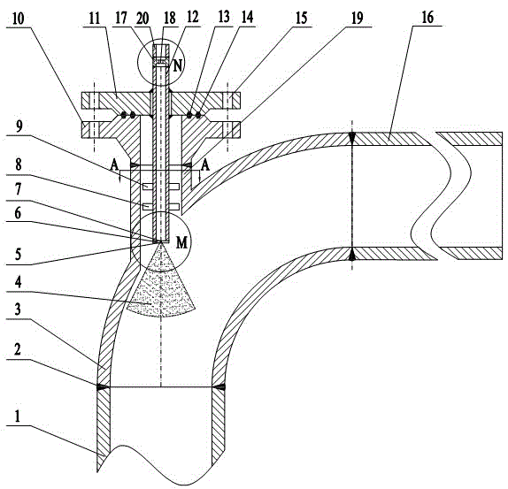
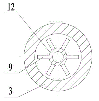
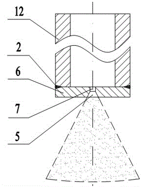
[0021] Such as figure 1 , figure 2 , image 3 with Figure 4 As shown, the present invention includes 90 o Elbow 3, injection pipe 12, lower flange 10, upper flange 11, atomizing nozzle 6, restrictor orifice 17 and injection sleeve 19; 90 o Elbow 3 backs are vertically provided with injection sleeve pipe 19, and injection sleeve pipe 19 lower ends and 90 o The elbow 3 is cast to form an integrated combined elbow. The upper end of the injection sleeve 19 is fixedly connected to the lower end surface of the lower flange 10 through the butt welding seam 2 . The first sealing ring 13 and the second sealing ring 14, both sealing rings are "O" type elastic sealing rings, the upper flange 11 and the lower flange 10 are connected by bolts through the bolt holes 15 around, and the injection pipeline 12 is in turn Insert from upper flange 11, lower flange 10, injection sle...


PUM


Abstract

The invention discloses a technological injectant device for controlling flow-induced corrosion failure of pipelines. An injectant sleeve is vertically arranged on the back of a 90-degree bend to form a combined elbow, the upper end of the combined elbow is fixedly connected with the lower end face of a lower flange, a sealing ring is arranged between an upper flange and the lower flange, an injectant pipeline is inserted into the elbow from the upper and lower flanges, the lower end face of the injectant pipeline is fixedly connected with an atomizing nozzle, two radial plates on the outer wall of the lower end of the injectant pipeline and the injectant sleeve form a floating support, the injectant pipeline is fixed in an upper flange hole, and the injectant pipeline located outside the upper flange is communicated with a third straight pipe section via a restriction orifice. Two ends of the elbow are communicated with a first straight pipe section and a second straight pipe section respectively. The injectant sleeve and the elbow are cast integrally, and reliability of high-pressure injectant is guaranteed; as the atomizing nozzle is arranged, injected injectant is atomized into small droplets to be fully mixed with an oil-gas phase medium in the elbow, and risk of dew point corrosion of the multiphase flow medium or corrosion caused by ammonium salt crystallization deposit is lowered; due to the restriction orifice, self-balancing effect during multi-point simultaneous injection when multiple air coolers or heat exchangers are connected in parallel is enhanced.

Description

technical field [0001] The invention relates to a nozzle atomization structure device, in particular to a process injection device for controlling pipeline flow corrosion failure. Background technique [0002] Petrochemical, coal chemical and other industries are one of the important driving forces to promote the continuous development of the social economy, and have a decisive influence on the economic development and social stability of the entire country. In petrochemical, coal chemical and other process industries, the process injection (injection) point and process mixing point are important components set up to meet production needs and maintain stable operation of the device. According to incomplete statistics, at present, there are different pressures, different temperatures, and different medium composition process mixing points and various injection agents such as corrosion inhibitors, scale inhibitors, oxidizers, neutralizers, and water in petrochemical system ref...

Claims


Application Information

Patent Timeline
IPC IPC(8): B01J19/26B01J4/00B05B1/04F16L55/00
Inventor 金浩哲偶国富贾剑鹏
Owner ZHEJIANG SCI-TECH UNIV
Learn More