
Compacting table for casting moulding

A vibrating table and molding technology, which is applied in the direction of casting molding equipment, molding machines, manufacturing tools, etc., can solve the problems of vibration of peripheral equipment and buildings, the level of the vibrating table surface, and the impact on the lives of surrounding residents, etc., to achieve surface quality Good, improve the safety production capacity, the effect of high compaction rate

Inactive Publication Date: 2015-09-23
QINHUANGDAO DEV ZONE CHUNGUANG CASTING MACHINERY
View PDF6 Cites 7 Cited by
  • Summary
  • Abstract
  • Description
  • Claims
  • Application Information

AI Technical Summary

Problems solved by technology

[0003] 1. Rubber air spring lifting vibration isolation form. This form of vibrating table relies on the inflation and exhaust of rubber air springs to ensure the lifting of the vibrating frame. This form of vibrating table vibrates when the vibrating frame is working. The table top cannot be kept level, and the molding sand is not evenly compacted
[0004] 2. Cylinder lifting rubber composite spring vibration isolation form. This form of vibrating table relies on the inflation and exhaust of the cylinder to ensure the lifting of the roller frame, while the vibrating frame itself remains unchanged, and the excitation force of the vibration motor is the highest. It is easy to be transmitted to the equipment foundation, causing the surrounding equipment and buildings to vibrate together, affecting the lives of the surrounding residents
[0005] 3. Cylinder lifting polyurethane rubber plate vibration isolation form. This form of vibrating table relies on the inflation and exhaust of the cylinder to ensure the lifting of the roller frame. Similarly, the vibrating frame itself remains unchanged, and the excitation of the vibration motor The force is also the easiest to transmit to the equipment foundation, and the amplitude is relatively small, so it is not easy to adjust
It will also cause surrounding equipment and buildings to vibrate together, affecting the lives of surrounding residents

Method used


Image

  • Compacting table for casting moulding
  • Compacting table for casting moulding

Examples


Embodiment Construction

[0013] The specific embodiment of the present invention will be described with reference to the accompanying drawings.

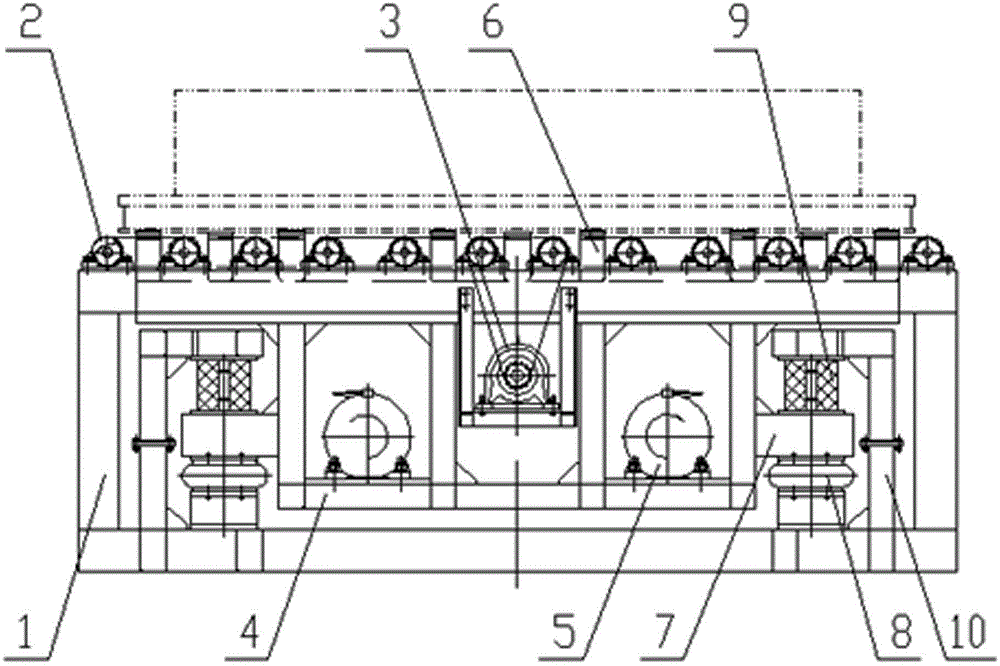
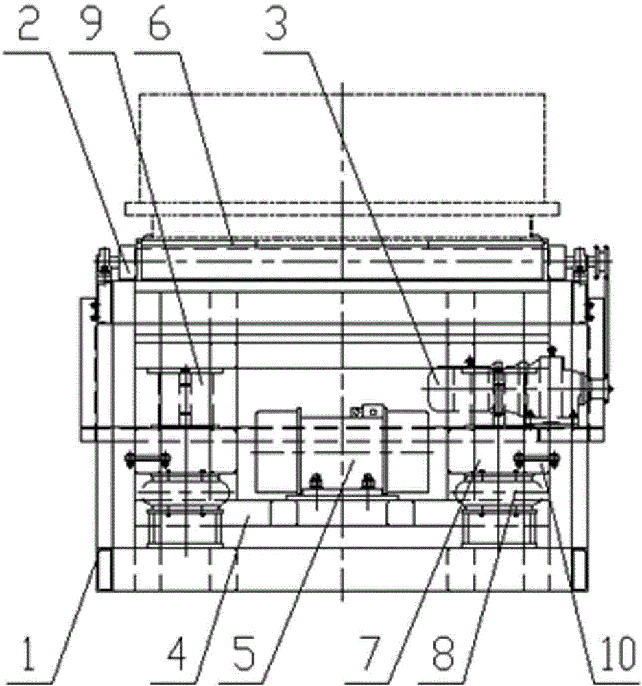
[0014] Such as figure 1 , figure 2 , The vibration table for casting molding includes a roller frame 1, and the roller frame 1 is fixed on the equipment foundation. On the roller table frame 1, idler rollers 2 are arranged transversely, and each idler roller 2 is installed on the surface of the roller table frame 1 through a bearing with a seat. The idler driving mechanism 3 is composed of a reduction motor and a sprocket chain transmission mechanism arranged on the roller frame 1 . A vibrating frame 4 is arranged inside the roller table frame 1, and the vibrating frame 4 is a rectangular frame structure. Vibration motor 5 is arranged at the bottom of vibrating frame 4, as the accompanying drawing embodiment, vibration motor 5 is arranged symmetrically a pair of left and right. The upper end of the vibrating frame 4 is provided with a joist 6 arranged t...


PUM


Abstract

A compacting table for casting moulding comprises a roller way frame, supporting rollers and a supporting roller driving mechanism. A compacting frame is arranged in the roller way frame, a vibrating motor is arranged on the lower portion of the compacting frame, supporting beams which are transversely arranged among the supporting rollers are arranged at the upper end of the compacting frame, spring assembling seats protruding out of the left side face and the right side face of the compacting frame are distributed on the lower portion of the compacting frame, a rubber air spring is arranged on the lower side of each spring assembling seat, a rubber spring is arranged on the upper side of each spring assembling seat, each rubber air spring and the corresponding rubber spring form a spring combination, a compacting frame seat is arranged on one side of each spring combination, the lower end of each rubber air spring corresponding to the corresponding compacting frame seat is fixed on th eupper side of a bottom seat body at the lower end of the corresponding compacting frame seat, and the upper end of each rubber spring corresponding to the corresponding compacting frame seat is matched with the lower side of an upper seat body at the upper end of the corresponding compacting frame seat. By the compacting table, moulding quality and efficiency can be improved effectively, equipment noise and influence on a workshop foundation during vibration can be reduced substantially.

Description

technical field [0001] The invention relates to casting molding mechanical equipment, in particular to a vibration table for casting molding. Background technique [0002] At present, the vibrating table used by the molding and core wire vibrating department of the foundry industry generally has the following three forms. [0003] 1. Rubber air spring lifting vibration isolation form. This form of vibrating table relies on the inflation and exhaust of rubber air springs to ensure the lifting of the vibrating frame. This form of vibrating table vibrates when the vibrating frame is working. The table cannot be kept level, and the molding sand is not evenly compacted. [0004] 2. Cylinder lifting rubber composite spring vibration isolation form. This form of vibrating table relies on the inflation and exhaust of the cylinder to ensure the lifting of the roller frame, while the vibrating frame itself remains unchanged, and the excitation force of the vibration motor is the high...

Claims


Application Information

Patent Timeline
Patent Type & Authority Applications(China)
IPC IPC(8): B22C15/10
Inventor 陈锡祥姜永录李国栋
Owner QINHUANGDAO DEV ZONE CHUNGUANG CASTING MACHINERY
Learn More