
Roller Conveyor for Drying Furnace

A technology for drying furnaces and conveyors, which is applied in the direction of conveyor objects, rollers, roller tables, etc., which can solve the problems of fixed-point heating and cooling of devices, easy volatilization of lubricating oil, large cavity of devices, etc., and achieve compensation for thermal expansion Cold shrinkage, simplified installation and commissioning, and multi-level change effects

Active Publication Date: 2018-05-08
AUTOMOTIVE ENG CORP +1
View PDF8 Cites 0 Cited by
  • Summary
  • Abstract
  • Description
  • Claims
  • Application Information

AI Technical Summary

Problems solved by technology

However, it can only operate continuously, and cannot heat and cool the device at a fixed point. At the same time, the cavity below the device is large, and the heat loss is high. Moreover, the temperature of the electrophoresis furnace is close to 200°C, and the chain is in the high temperature zone of the furnace. The lubricating oil is volatile and accumulates. carbon, and the cost of lubrication is high
[0004] The IMC conveyor also has the disadvantages that it can only run continuously, cannot perform fixed-point heating and cooling on the device, and has a large cavity under the device and high heat loss. Moreover, the pitch of the device is large, and the length of the drying furnace is about 15% larger than that of the double-chain furnace. ,higher cost

Method used


Image

  • Roller Conveyor for Drying Furnace
  • Roller Conveyor for Drying Furnace
  • Roller Conveyor for Drying Furnace

Examples


Embodiment Construction

[0021] The present invention will be described in further detail below in conjunction with the accompanying drawings and specific embodiments. It should be understood that the specific embodiments described here are only used to explain the present invention, not to limit the present invention.

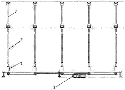
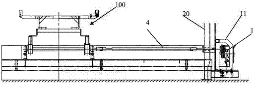
[0022] Such as Figure 1-5 As shown, the roller conveyor for drying furnace of the present invention includes multiple groups of conveying units arranged in sequence, and the conveying unit includes a driving motor 1 fixedly arranged on the bottom outside of the drying furnace, and a plurality of them are connected to the The drive motor is connected through the sprocket chain transmission and runs through the transmission shaft 2 of the furnace wall of the drying furnace, a plurality of conveying rollers 3 arranged at the bottom of the drying furnace at intervals, and the conveying rollers and the transmission shaft are arranged one by one Corresponding to the connected high-tempera...


PUM


Abstract

The invention discloses a roller conveyer for a drying oven. The roller conveyer comprises multiple sets of conveying units arranged in sequence, wherein the conveying units comprise driving motors fixed at the bottom of the outer side of the drying oven, multiple transmission shafts in transmission connection with the driving motors and penetrating through the wall of the drying oven, multiple conveying rollers arranged at the bottom of the drying oven at intervals, and high-temperature resisting telescopic universal couplings for correspondingly connecting the conveying rollers with the transmission shafts one to one; bearings at one ends of the conveying rollers are fixed corresponding to bearing bases; and bearings at the other ends of the conveying rollers are mounted in a floating manner to compensate the heat expansion and cold contraction of the rollers and the bottom of the oven. The roller conveyer adopts multiple sets of singly arranged conveying units; each conveying unit is allocated with single driving motor; chain wheel and chain mechanisms outside the oven are used for driving the conveying rollers to rotate; and conveying wheels on the conveying rollers are adopted to support and transmit such devices as conveying sledges of white car bodies, so that the transmission stability is strong, and the single drive control is achieved.

Description

technical field [0001] The invention relates to the technical field of painting, in particular to a roller conveyor for a drying furnace. Background technique [0002] In mechanical processing, it is often necessary to dry the device. For example, the body-in-white needs to be dried at high temperature after electrophoresis. Convey forward and finish drying during conveying. [0003] For the drying of the body in white, the car drying now uses a drying double-chain conveyor and an IMC conveyor. The conveyor chain and frame of the drying double-chain conveyor are arranged in the furnace and run continuously. However, it can only operate continuously, and cannot heat and cool the device at a fixed point. At the same time, the cavity below the device is large, and the heat loss is high. Moreover, the temperature of the electrophoresis furnace is close to 200°C, and the chain is in the high temperature zone of the furnace. The lubricating oil is volatile and accumulates. Carbo...

Claims


Application Information

Patent Timeline
Patent Type & Authority Patents(China)
IPC IPC(8): B65G13/07
CPCB65G13/02B65G13/07B65G39/09
Inventor 林涛戈北京朱本正王升建戴旻高春生
Owner AUTOMOTIVE ENG CORP
Learn More