Pit-type nitriding furnace

A technology of nitriding furnace and furnace cover, applied in coating, metal material coating process, solid-state diffusion coating, etc., can solve problems such as failure to meet customer requirements, uneven heating of inner furnace, inconsistent product hardness, etc. Achieve equipment durability, improve utilization and productivity, and achieve consistent hardness

Inactive Publication Date: 2015-09-23
浙江长兴天盛工业炉有限公司
View PDF5 Cites 8 Cited by
  • Summary
  • Abstract
  • Description
  • Claims
  • Application Information

AI Technical Summary

Problems solved by technology

[0002] The well-type nitriding furnace is a barrel-shaped structure, which is generally used for thermal processing of parts such as injection molding machines, braiding machine barrels, and screws. For many years, ordinary nitriding furnaces produced by general manufacturers use ordinary 321 stainless steel furnaces, and The nitriding furnace is not equipped with a fan, the uniformity of the furnace temperature is poor, the cooling speed is slow, and the hardness of the product is inconsistent, which cannot meet the customer's requirements
[0003] The inner furnace of the ordinary well-type nitriding furnace has been in a high-temperature and high-pressure working environment for a long time, and the inner furnace is heated unevenly, which causes the inner furnace to be easily deformed and affects the service life; the furnace shell of the ordinary well-type nitriding furnace and There is only one layer of lining made of refractory material between the inner furnaces, and the heat loss is high, which makes the energy consumption of the nitriding furnace high and the processing efficiency is low

Method used


Image

  • Pit-type nitriding furnace

Examples


Embodiment Construction

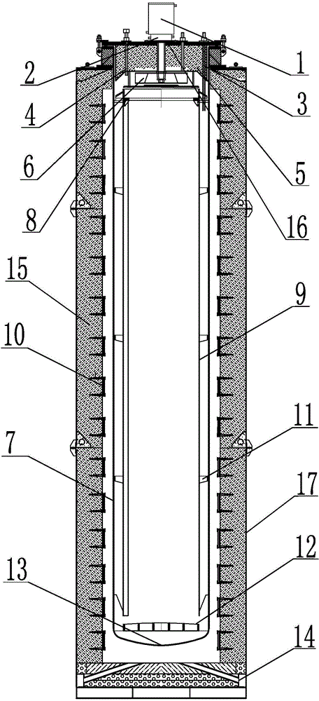
[0014] The specific implementation manner of the present invention will be described in detail below in conjunction with the accompanying drawings.

[0015] like figure 1 A well-type nitriding furnace shown includes a furnace shell 17, a furnace cover 16, an inner furnace 7 and an air guide barrel 9, the furnace cover 16 is installed on the top of the furnace shell 17, and the furnace shell 17 inner wall A layer of furnace lining 15 is provided, and a heating element 10 is evenly installed on the inner wall of the furnace lining 15. The heating element 10 is a resistance band, and the resistance band is fixed on the inner wall of the furnace lining 15 through a ceramic screw rod, which has a simple structure and is easy to install. It is easy to replace, improves the radiation coefficient of the electric heating element, strengthens the heat exchange in the furnace, improves the thermal efficiency of the furnace, prolongs the service life of the element, and improves the quali...


PUM

PropertyMeasurementUnit
thicknessaaaaaaaaaa
thicknessaaaaaaaaaa
hardnessaaaaaaaaaa

Abstract

The invention relates to a pit-type nitriding furnace. The pit-type nitriding furnace comprises a furnace shell, a furnace cover, an inner furnace container and a wind guide barrel. The inner furnace container is arranged inside the furnace shell. The wind guide barrel with the two ends open is hung in the inner furnace container. A tripod is arranged between the wind guide barrel and the inner furnace container for supporting. The bottom of the inner furnace container is an arc surface. A furnace container bottom board is arranged at the position where the bottom of the inner furnace container and an inner furnace container body are connected and is provided with holes. A draught fan is fixed in the middle of the upper end of the furnace cover. A cooling water tank is arranged between the draught fan and the furnace cover. A heat collection box is fixed to the lower end of the furnace cover. The draught fan is connected with a blade through a shaft penetrating through the heat collection box. The draught fan is arranged on the furnace cover, the wind guide barrel is arranged inside the inner furnace container, and the draught fan and the inner furnace container are matched, so that gas is emitted and circulates from bottom to top and heat inside the furnace is distributed more uniformly. The tripod is arranged between the wind guide barrel and the inner furnace container and further improves the intensity of the inner furnace container, and the inner furnace container can be effectively prevented from deforming.

Description

technical field [0001] The invention relates to heat treatment equipment, in particular to a well type nitriding furnace. Background technique [0002] The well-type nitriding furnace is a barrel-shaped structure, which is generally used for thermal processing of parts such as injection molding machines, braiding machine barrels, and screws. For many years, ordinary nitriding furnaces produced by general manufacturers use ordinary 321 stainless steel furnaces, and The nitriding furnace is not equipped with a fan, the temperature uniformity of the furnace is poor, the cooling speed is slow, and the hardness of the product is inconsistent, which cannot meet the customer's requirements. [0003] The inner furnace of the ordinary well-type nitriding furnace has been in a high-temperature and high-pressure working environment for a long time, and the inner furnace is heated unevenly, which causes the inner furnace to be easily deformed and affects the service life; the furnace sh...

Claims


Application Information

Patent Timeline
Patent Type & Authority Applications(China)
IPC IPC(8): C23C8/26
Inventor 钱亚俊
Owner 浙江长兴天盛工业炉有限公司
Why Eureka
Try Eureka