
System with potential balancing component, particularly battery system

A technology of potential balance and components, which is applied to electrical components, batteries, secondary batteries, etc., and can solve problems such as damage to battery system components, disconnection of protective relays, and electric shocks to personnel

Active Publication Date: 2015-09-23
ROBERT BOSCH GMBH
View PDF9 Cites 3 Cited by
  • Summary
  • Abstract
  • Description
  • Claims
  • Application Information

AI Technical Summary

Problems solved by technology

[0008] There is also the problem that in the event of an insulation fault on an internal system component and another insulation fault on an external component, such as a high voltage cable of the vehicle in which the system is used, the insulation on the outside of the system The protective relay for galvanic separation of the system from the vehicle opens before the fault is recognized
If the battery system is switched on again by closing the protective relay in such a case, although the external insulation fault continues or is even aggravated, then in particular via electrically conductive battery system components such as heat sinks and electrically conductive Accidental contact of battery housing components additionally generates a short-circuit current that further damages the battery system components
In addition, if different potentials are applied to different housing parts, there is also the risk of people being electrocuted by touching the vehicle

Method used


Image

  • System with potential balancing component, particularly battery system
  • System with potential balancing component, particularly battery system
  • System with potential balancing component, particularly battery system

Examples


Embodiment Construction

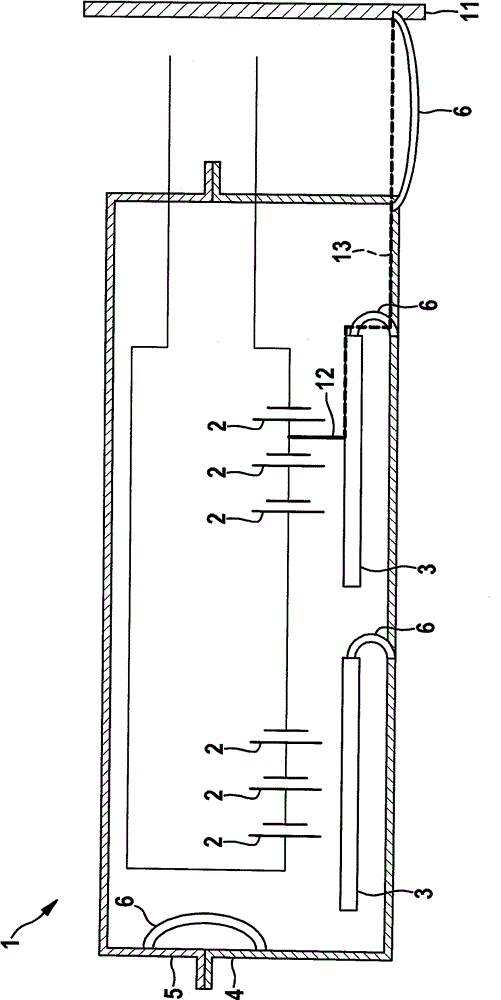
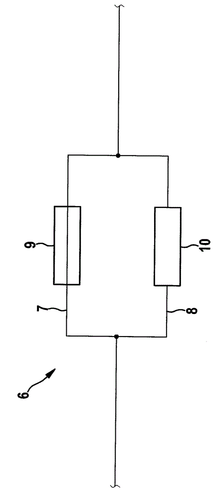
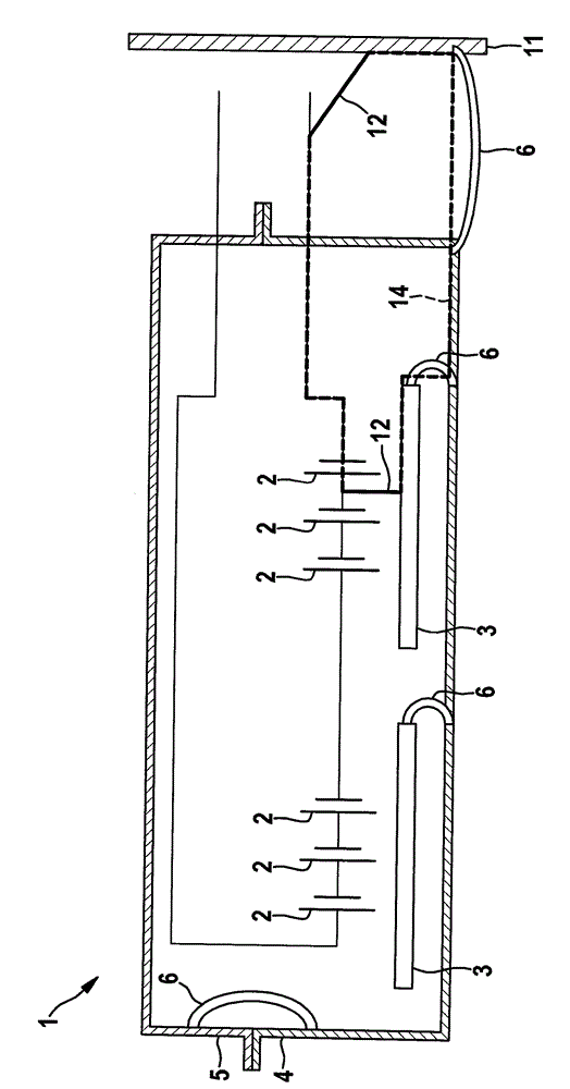
[0027] exist figure 1 An exemplary embodiment for a potential equalization element 6 which is provided for use in the system according to the invention is shown in FIG. The potential balancing element 6 includes a parallel circuit including a potential balancing path 7 and a short-circuit current limiting path 8 . The potential equalization path 7 here includes a fuse element 9 which, in the exemplary embodiment, is designed as a fuse. In particular, safety element 9 is designed to trigger and disconnect potential equalization path 7 if the current in potential equalization path 7 exceeds a predefined limit value. The potential equalization path 7 is also designed in a low-ohmic form, that is to say that the potential equalization path 7 has no resistance, especially as a structural element, but the resistance is determined only by the unit resistance of the material and by the geometrical dimensions of the potential equalization path 7 Sure. In particular, the potential eq...


PUM


Abstract

The invention relates to a system (1) which is provided with system components (2) that are interconnected electrically. The system components are at least partially electrified and comprise at least one additional system component (3,4,5) which is conductive. The at least one additional system component (3,4,5) is placed on a ground potential (11) by means of at least one potential balancing component (6). The potential balancing component (6) comprises a parallel circuit which is composed of a potential balancing path and a shortcircuit current limiting path. Compared with the shortcircuit current limiting path, the potential balancing path has a smaller resistance in a manner that a potential balancing current which is lead out of the at least one additional system component (3,4,5) through the potential balancing component (6) basically flows in the potential balancing path, and furthermore the potential balancing path can be switched off when the current in the potential balancing path exceeds a preset boundary value.

Description

technical field [0001] The invention relates to a system, in particular a battery system, having system components electrically connected to one another, which are at least partially live and having at least one further system component which is Conductive, wherein the at least one further system component is brought to ground potential by means of at least one potential equalization element. Background technique [0002] The system mentioned at the outset within the meaning of the present invention is in particular a system for supplying electrical energy in a hybrid vehicle, a plug-in hybrid vehicle or an electric vehicle. In particular, this refers to battery systems that have a plurality of battery cells that are electrically connected to one another, in particular battery cells that are electrically connected to one another to form a battery module. Furthermore, this also refers to other electrical systems, in particular fuel cell systems. Systems of this type have a ...

Claims


Application Information

Patent Timeline
Patent Type & Authority Applications(China)
IPC IPC(8): H02H9/02H01M10/48
CPCH02H3/087H02H3/105H02H9/041H01M10/441H01M10/482H01M10/486H01M2200/103Y02E60/10H01M50/581
Inventor G.加拉姆布
Owner ROBERT BOSCH GMBH
Learn More