
Full digitalization LED lighting source driving control system and technical scheme

A technology of LED lighting and light source driving, applied in the direction of light source, electric light source, lighting device, etc., can solve the problem of multi-channel independent constant current driver not working normally, the working voltage of multi-channel independent constant current driver is not enough, unable to work normally, etc. Achieve high stability, improve service life, and achieve color effects

Active Publication Date: 2015-09-23
华夏网络科技服务南京有限公司
View PDF3 Cites 4 Cited by
  • Summary
  • Abstract
  • Description
  • Claims
  • Application Information

AI Technical Summary

Problems solved by technology

In the original utility model patent, a DC / DC conversion module on the control board of the single-chip microcomputer is used to generate a low voltage of 5V, which is transmitted from one level to the next through a dedicated transmission line, which brings about a problem. When the transmission distance is long (For large-area lighting sources), it will appear that the multiple independent constant current drivers mentioned later cannot work normally due to insufficient operating voltage due to road end loss.
Secondly, as mentioned above, the serial digital signals required by the multi-channel independent constant current drivers in each stage will also be attenuated due to the long transmission distance. The streaming drive just doesn't work

Method used


Image

  • Full digitalization LED lighting source driving control system and technical scheme
  • Full digitalization LED lighting source driving control system and technical scheme

Examples


Embodiment Construction

[0021] In order to better understand the technical solutions of the present invention, the embodiments provided by the present invention will be described in detail below in conjunction with the accompanying drawings.

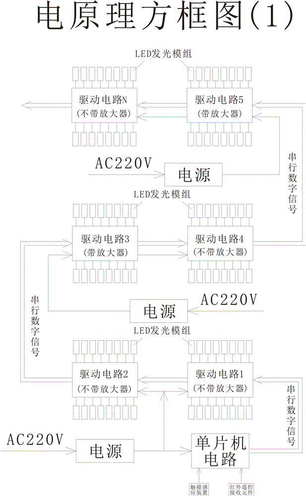
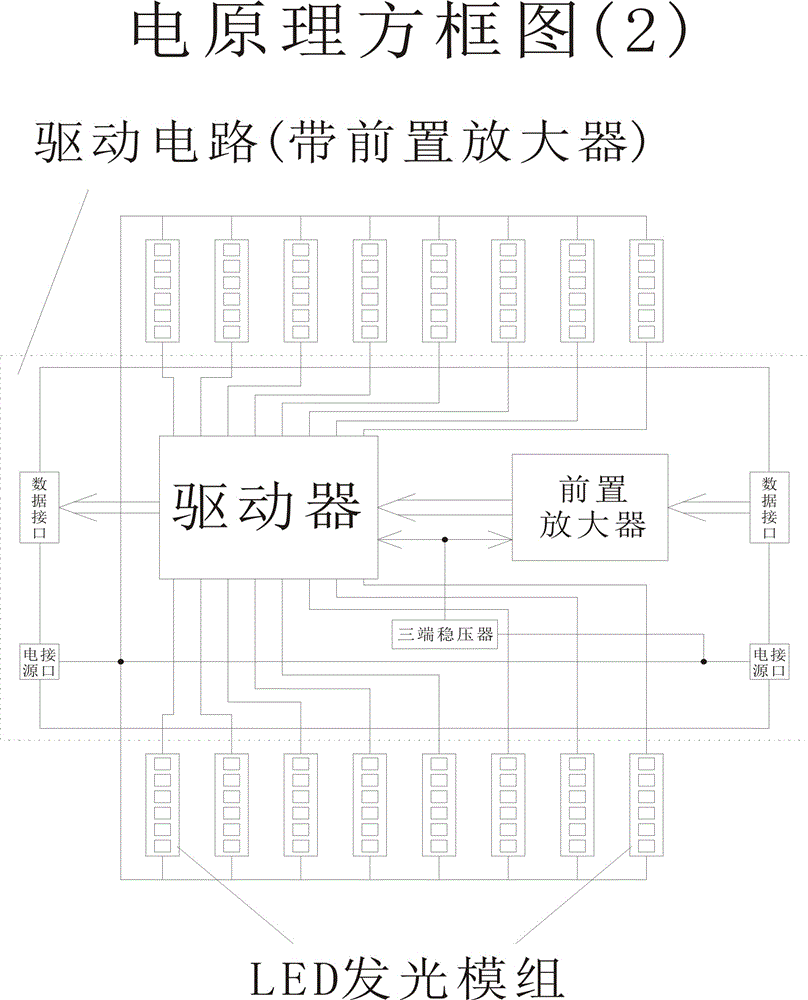
[0022] 1. Rudian principle box figure 1 As shown, the microcontroller circuit outputs programmed serial digital signals to control drive circuit 1, drive circuit 2, ... drive circuit N. Preferably, each of the driving circuits is composed of a pre-signal amplifier (or not installed), a driver, a three-terminal voltage regulator, and data, power input, and output connectors, see the electrical principle box figure 2 shown.

[0023] 2. Rudian Principle Box figure 1 As shown, each driving circuit can drive a plurality of LED light emitting modules connected in series (or a plurality of LED light emitting modules connected in common anode), such as 16. Preferably, each of the LED light-emitting modules has a plurality of LED lamp beads connected in series on ...


PUM


Abstract

The present invention provides a full digitalization LED lighting source driving control system and technical scheme, relates to the technical field of LED lighting source driving control, and especially relates to a large-area LED lighting source driving control technology. A single-chip microcomputer outputs a programmed serial digital signal for controlling an unlimited number of drive circuits, wherein the drive circuits can drive multiple LED luminescence modules. In this way, the technical scheme overcomes the disadvantages that driving of a constant voltage source cannot achieve constant current while driving of a constant current source cannot achieve current sharing, thereby effectively prolonging the service life of an LED light source. At the same time, as the system of the present invention adopts single-chip microcomputer full digitalization control, the drive circuit not only can drive a plurality of LED luminescence modules connected in series for achieving point-to-string control, but also can drive a plurality of LED luminescence modules connected in a common-anode mode for achieving point-to-point control. Therefore, high-stability large-area illumination can be easily achieved, various forms of illumination changes can be achieved at will through digital programming, and infinite color changes also can be achieved if color LED lamp beads are driven, thus wide application prospect can be achieved.

Description

technical field [0001] The invention relates to the technical field of driving control of LED lighting sources, in particular to a driving control technology of large-area LED lighting sources. Background technique [0002] 1. The existing LED lighting source drive circuits have deficiencies. As a new generation of solid-state light source, LED is characterized by the fact that it must work under DC and low voltage conditions. The stability and consistency of the current during operation directly determines the service life of the LED. At the same time, LED is a point light source with a small lighting area. To achieve large-area lighting, it is necessary to combine many LEDs together, and the DC safety voltage should generally be below 36V. In this case, the combination of LEDs can only be used. The combination of series and parallel, according to the law of loop current in the circuit, the current flowing through each device in the series circuit is equal, and the current...

Claims


Application Information

Patent Timeline
IPC IPC(8): H05B37/02
Inventor 汪静
Owner 华夏网络科技服务南京有限公司
Learn More