Lifting handle device mounted on submersible flow pushing device

A submersible flowmaker and short-rod technology, applied in water aeration, transportation and packaging, chemical instruments and methods, etc., can solve problems such as unfavorable work development, center of gravity offset, submersible flowmaker lifting and tilting, etc., to save Effects of processing material resources and processing costs

Active Publication Date: 2015-09-30
LANSHEN GRP CORP LTD
View PDF5 Cites 1 Cited by
  • Summary
  • Abstract
  • Description
  • Claims
  • Application Information

AI Technical Summary

Problems solved by technology

[0003] When the current submersible flowmaker is lifted, a handle is installed on the main unit of the equipment, but different specifications of submersible flowmakers have different technical parameters, so it is usually after the equipment is manufactured to find out the center of gravity of the submersible flowmaker. Then according to the center of gravity of the submersible flowmaker, a matching handle is specially made, but a handle is specially made for each submersible flowmaker. The quantity is huge, which not only wastes resources, but also increases the cost. The addition of a certain amount of lubricating oil will also cause the center of gravity to shift. The specially made handle is likely to cause a deviation in the lifting center of gravity in actual use, which will cause the submersible thruster to tilt or jam when it goes up and down, which is not conducive to the development of follow-up work.

Method used


Image

  • Lifting handle device mounted on submersible flow pushing device
  • Lifting handle device mounted on submersible flow pushing device
  • Lifting handle device mounted on submersible flow pushing device

Examples


Embodiment Construction

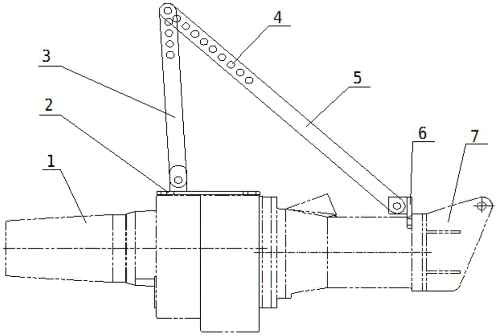
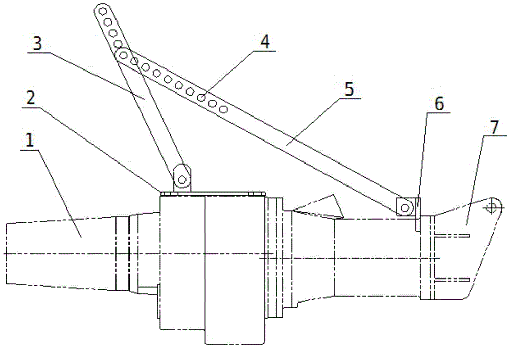
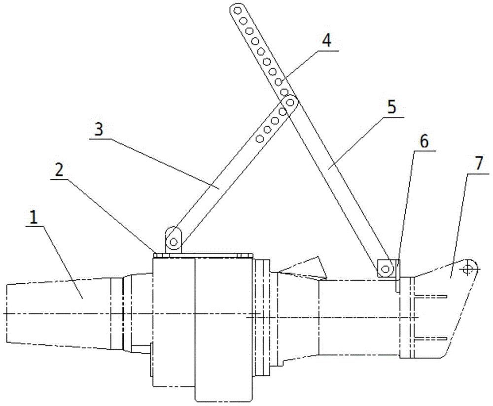
[0015] Such as Figures 1 to 5 As shown, the present invention is a handle device installed on a submersible flow booster, including a host connecting plate 2, a handle short rod 3, a handle long rod 5 and a sliding sleeve connecting plate 6, and one end of the handle short rod 3 There are five hinged holes 4, one end of the long handle 5 is provided with ten hinged holes 4, the short handle 3 and the long handle 5 are not provided with hinged holes 4, and one end of the handle is connected with the host connecting plate 2 and the sliding sleeve respectively. Plate 6 is hinged.

[0016] When the present invention is in use, the host connecting plate 2 is fixed at the middle front part of the host 1 by fasteners, and the sliding sleeve connecting plate 6 is fixed behind the host 1 with fasteners, that is, the connection between the host 1 and the sliding sleeve 7 place. Then match the hinged holes 4 on the short handle 3 with the long handle 5 one by one until the lifting cen...


PUM


Abstract

The invention relates to a lifting handle device mounted on a submersible flow pushing device. The lifting handle device comprises a main machine connection plate, a lifting handle short rod, a lifting handle long rod and a slide sleeve connection plate, wherein one end of the lifting handle short rod and one end of the lifting handle long rod are provided with a plurality of hinging holes respectively; and the other end of the lifting handle short rod and the other end of the lifting handle long rod are hinged with the main machine connection plate and the slide sleeve connection plate respectively. When the lifting handle device is used, the main machine connection plate is fixed at the front middle part of a main machine through a fastening piece, and the slide sleeve connection plate is fixed behind the main machine through the fastening piece; then the hinging holes of the lifting handle short rod and the lifting handle long rod are matched gradually until the hoisting gravity center point of the submersible flow pushing device is found; the lifting handle device can be used on submersible flow pushing devices with different specifications; the machining material resources and the machining cost are saved; the schedule and quality of mounting, maintaining and overhauling the submersible flow pushing device can be ensured; and the hoisting gravity center can be adjusted at any time according to actual working conditions, so that the lifting handle device is very practical and convenient and is suitable for general popularization and application.

Description

technical field [0001] The invention relates to a handle device installed on a submersible flow thruster. Background technique [0002] Submersible pushers are widely used in industrial and urban sewage treatment plant processes. The low-tangential, open and strong water flow generated by them can be used for water circulation in pools and for creating water flows in the stages of nitrification, denitrification and phosphorus removal. Submersible pushers When installing, maintaining and overhauling the flow device, the main engine should be lifted or sunk in the pool through the lifting device. Usually, a sliding sleeve is installed behind the main engine, and then the guide rod is fixed on the wall of the pool, and then the lifting device Under the action of the device, the sliding sleeve reciprocates up and down on the guide rod, thereby smoothly lifting and placing the submersible flowmaker. However, if this process is to be successfully completed, it is very important t...

Claims


Application Information

Patent Timeline
Patent Type & Authority Applications(China)
IPC IPC(8): B66C1/10C02F7/00
CPCB66C1/10B66C13/08C02F7/00Y02W10/10
Inventor 陈晓军叶彩霞
Owner LANSHEN GRP CORP LTD
Why Eureka
Try Eureka