Supercharge Your Innovation With Domain-Expert AI Agents!

Stepless flow control device

A flow control device, a stepless technology, which is applied to wellbore/well valve devices, production fluids, wellbore/well components, etc., can solve problems such as poor reliability, achieve safe and reliable use, and meet the needs of fine flow control and adjustment. handy effect

Active Publication Date: 2015-09-30
CHINA UNIV OF PETROLEUM (EAST CHINA)
View PDF8 Cites 9 Cited by
  • Summary
  • Abstract
  • Description
  • Claims
  • Application Information

AI Technical Summary

Problems solved by technology

Since the downhole flow control device works in a high temperature and high pressure environment, the reliability of the electric drive method is poor, and it is still in the laboratory

Method used


Image

  • Stepless flow control device
  • Stepless flow control device
  • Stepless flow control device

Examples


Embodiment Construction

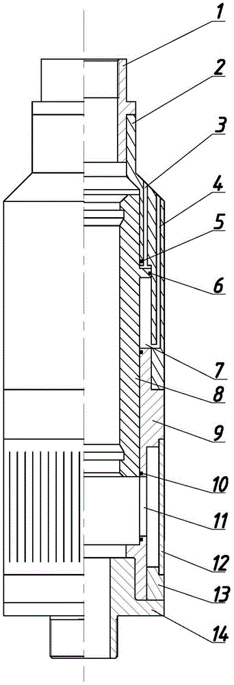
[0022] like Figure 1-3 As shown, the stepless flow control device includes: an upper joint 1, an upper outer sleeve 2, an inner sliding sleeve 8, a lower outer sleeve 9, a slotted screen 12, a screen fixing block 13, and a lower joint 14; wherein, the upper outer sleeve 2, The lower jacket 9 is connected by threads, and the upper jacket 2 and the lower jacket 9 are connected to form an inner cavity, and the inner sliding sleeve 8 is located in the inner cavity; the inner sliding sleeve 8, the upper jacket 2 and the lower jacket 9 form a piston cylinder 7; the upper jacket 2 is provided with an upper hydraulic passage 3 and a lower hydraulic passage 4, and the upper hydraulic passage 3 and the lower hydraulic passage 4 communicate with the upper and lower ends of the piston cylinder 7 respectively; the outer side of the inner sliding sleeve 8 has a cylindrical step 81, and the cylindrical step 81 It forms a gap fit with the wall surface of the piston cylinder 7, and realizes a...


PUM


Abstract

The invention belongs to the field of petroleum engineering, and particularly relates to a stepless flow control device. The stepless flow control device comprises an upper connector, an upper outer cover, an inner sliding cover, a lower outer cover, a slotted screen pipe, a screen pipe fixing block and a lower connector. The upper outer cover is connected with the lower outer cover through a thread to form an inner cavity. The inner sliding cover is arranged inside the inner cavity. A piston cylinder is formed by surrounding of the inner sliding cover, the upper outer cover and the lower outer cover. An upper hydraulic channel and a lower hydraulic channel are arranged inside the upper outer cover, and are communicated with the upper end and the lower end of the piston cylinder respectively. The outer side of the inner sliding cover is provided with a cylindrical step which is in clearance fit with the wall face of the piston cylinder in a clearance mode. The middle of the lower end of the lower outer cover is provided with a rectangular valve port. The slotted screen pipe is arranged outside the rectangular valve port. The upper connector is connected with the upper outer cover. The lower connector is connected with the lower outer cover. Positioning and locking can be carried out on the position of the movable inner sliding cover of the stepless flow control device by a three-position reversing valve and a bi-direction hydraulic lock at will, and therefore fine control on reservoir fluid can be achieved.

Description

technical field [0001] The invention belongs to the field of petroleum engineering, and in particular relates to a stepless flow control device, which is used for fine control of reservoir fluid in intelligent well completion. Background technique [0002] Reservoir flow control technology is the core of intelligent well completion. Through the cooperation of the flow control valve placed in the downhole reservoir and the packer, the pressure and flow of the reservoir are balanced, and the selectivity of each interval or branch of the reservoir is controlled. Injection or production can improve the production status of the oil well, and the flow control valve enables oilfield operators to change the flow characteristics of the interval more conveniently without mechanical workover operations. [0003] At present, there are two ways to adjust the valve opening of the downhole flow control valve used for reservoir flow regulation: hydraulic and electric. WellDynamics, Baker H...

Claims


Application Information

Patent Timeline
IPC IPC(8): E21B43/12E21B34/06
Inventor 相恒富李鹏飞陈春雷焉琳琳
Owner CHINA UNIV OF PETROLEUM (EAST CHINA)
Features
  • R&D
  • Intellectual Property
  • Life Sciences
  • Materials
  • Tech Scout
  • Unparalleled Data Quality
  • Higher Quality Content
  • 60% Fewer Hallucinations
Learn More