Energy-saving horizontal direct-connected single-stage double-suction centrifugal pump

A direct-connected single-stage, energy-saving technology, applied in the direction of non-variable pumps, pumps, pump components, etc., can solve the problem of temperature rise of motors and motor bearings, affecting motor performance and production efficiency, and double-suction centrifugal pumps occupying an area Large area and other problems, to achieve the effect of fewer failure points, convenient pump room layout, and convenient pipeline design and layout

Inactive Publication Date: 2018-02-27
姚庆义
View PDF5 Cites 0 Cited by
  • Summary
  • Abstract
  • Description
  • Claims
  • Application Information

AI Technical Summary

Problems solved by technology

[0002] The existing horizontal double-suction centrifugal pump is composed of pump body, pump cover, impeller shaft, impeller, motor, coupling, bearing, packing and other parts, which has the following problems: 1. The motor shaft and The impeller shafts are connected, relying on the coupling to transmit power, and the reactive power loss is large. At the same time, the double-suction centrifugal pump occupies a large area, and the mechanical transmission brings large noise and vibration, which affects the stability of the centrifugal pump operation and the mechanical failure rate. Higher; 2. Double-suction centrifugal pump pumping high-temperature liquid or working for a long time will easily cause the temperature of the motor and motor bearings to rise. In order to prevent damage to the motor, it usually needs to be shut down intermittently to cool down, which seriously affects the performance of the motor and production efficiency. ; 3. The coupling must be covered with a casing during operation to prevent the fasteners from being thrown out and hurting people. At the same time, the buffer rubber blocks are constantly squeezed and rubbed to produce odors and damage human health.
[0003] At present, in order to reduce the reactive power loss of centrifugal pumps, some centrifugal pumps adopt the method of direct connection without transition, that is, the motor shaft is extended and extended into the pump body to replace the impeller shaft, and the coupling is omitted, but this structure is only realized in single-stage It is not suitable for single-suction centrifugal pumps to be applied to double-suction centrifugal pumps. The reason is that it is limited by the internal structure of existing double-suction centrifugal pumps. The internal space formed by the pump body and pump cover of existing double-suction centrifugal pumps The partition wall is used to divide the suction vortex chamber on both sides and the discharge vortex chamber in the middle. The impeller is installed in the discharge vortex chamber in the middle and a double-suction sealing ring is installed between the partition wall. If the direct connection is adopted, the pump body and pump cover must use The upper and lower split structures, which lead to the fact that when the rotor part (impeller, etc.) in the pump is damaged, the pump cover must be opened and lifted first, then the motor and the rotor part are lifted together, and finally the lower impeller is removed from the motor shaft in turn The inspection, replacement or maintenance of positioning parts, impellers, seals, bearings and other components is cumbersome and complicated, and because the motor needs to be lifted together, it is time-consuming and laborious, which seriously affects work efficiency

Method used


Image

  • Energy-saving horizontal direct-connected single-stage double-suction centrifugal pump
  • Energy-saving horizontal direct-connected single-stage double-suction centrifugal pump

Examples


Embodiment 1

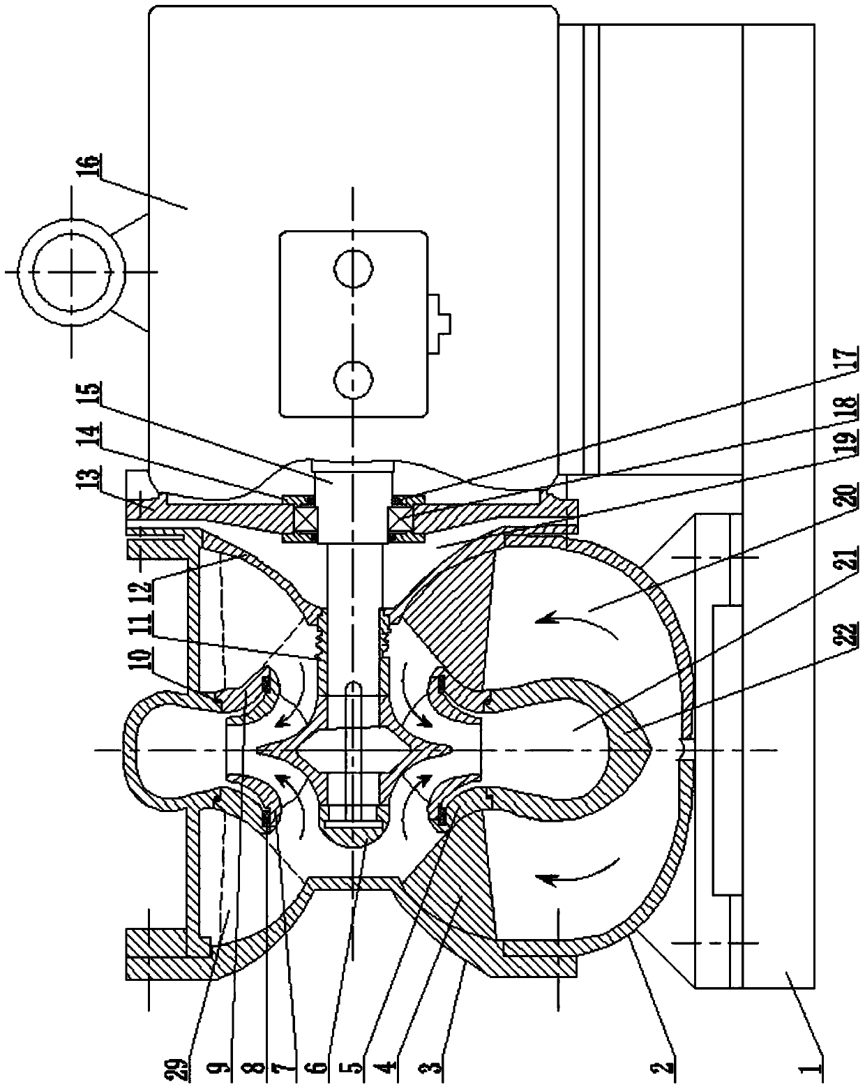
[0030] Such as figure 1 As shown, the energy-saving horizontal direct-connected single-stage double-suction centrifugal pump includes a pump body 2, a pump cover, an impeller 7 and a motor 16. The pump body 2 is provided with a suction vortex chamber 20 on both sides and a middle discharge vortex chamber 21. The pump cover is composed of the pump cover I3 and the pump cover II12 which are arranged on the left and right sides of the pump body 2 respectively. The side cover 13 of the motor 16 is connected and fixed with the pump cover II12 on the corresponding side, and an open air is provided between them. Isolate the gap 19, the motor shaft 15 passes through the pump cover II13 and enters the pump body 2, and the impeller 7 is installed on the motor shaft 15 corresponding to the center position of the middle discharge vortex chamber 21, and a bellows type dynamic valve is provided between the impeller 7 and the pump cover II12. Seal 11, the end of the motor shaft 15 is provid...

Embodiment 2

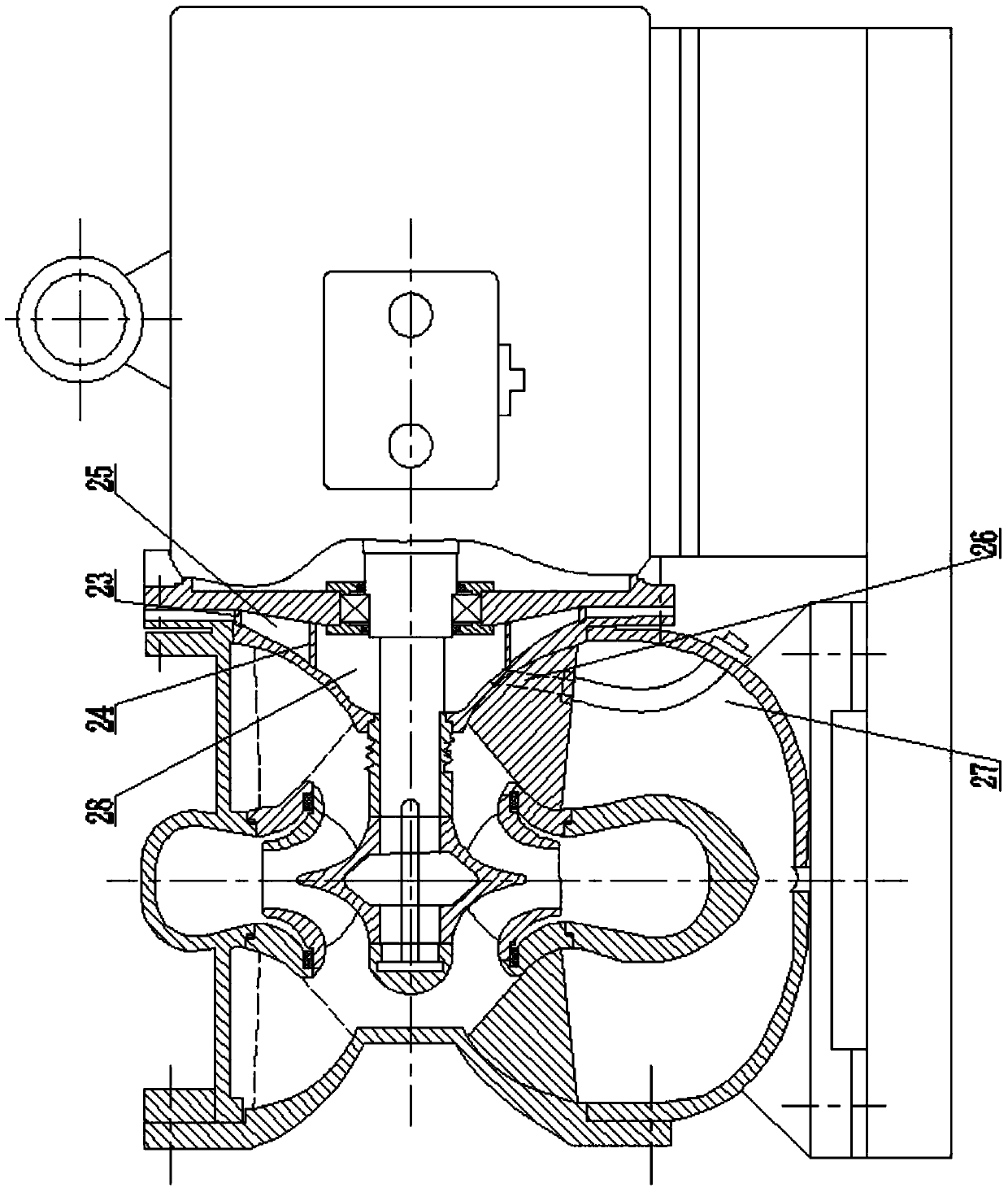
[0033] Such as figure 2As shown, in the energy-saving horizontal direct-connected single-stage double-suction centrifugal pump, the side cover 13 of the motor is connected and fixed to the pump cover II 12 on the corresponding side, and a cooling water isolation cavity 25 is arranged between the two. The side cover of the motor 13 is provided with concentric inner and outer annular male ports 24 and 23, and the pump cover II12 is provided with inner and outer annular female ports corresponding to the inner and outer annular male ports 24 and 23 respectively. The water isolation cavity 25 is surrounded by the side cover 13 of the motor, the pump cover II 12, and the inner and outer annular male seals 24, 23. The outer annular male seal 23 is respectively provided with an inlet and an outlet (omitted in the figure). In order to connect with the external cooling water system. The inner space 28 of the inner annular male stop 24 is provided with a discharge channel leading to th...


PUM


Abstract

The invention relates to an energy-saving horizontal double-suction centrifugal pump, which includes a pump body, a pump cover, an impeller and a motor. The connection between the motor side cover and the pump cover II is fixed, and there is an open air isolation gap or a cooling water isolation cavity between the two. The motor shaft passes through the pump cover II and enters the pump body, and the impeller corresponds to the center of the vortex chamber in the middle. Installed on the motor shaft, there is a bellows type dynamic seal between the impeller and the pump cover II, the suction vortex chamber on both sides of the pump body and the discharge vortex chamber in the middle are matched with the partition wall integrated with the pump body and the partition wall by using a spigot The left and right annular partitions are separated together, the center line of the left and right annular partitions coincides with the axis of the motor, and the left and right annular partitions and the corresponding side pump cover respectively use the connecting ribs to form an integrated structure. The outer diameters of the left and right annular partition plates are greater than the maximum diameter of the impeller. It is energy-saving and high-efficiency, and at the same time, it is convenient for repair and maintenance, and significantly improves work efficiency.

Description

technical field [0001] The invention relates to an energy-saving horizontal direct-connected single-stage double-suction centrifugal pump. Background technique [0002] The existing horizontal double-suction centrifugal pump is composed of pump body, pump cover, impeller shaft, impeller, motor, coupling, bearing, packing and other parts, which has the following problems: 1. The motor shaft and The impeller shafts are connected, relying on the coupling to transmit power, and the reactive power loss is large. At the same time, the double-suction centrifugal pump occupies a large area, and the mechanical transmission brings large noise and vibration, which affects the stability of the centrifugal pump operation and the mechanical failure rate. Higher; 2. Double-suction centrifugal pump pumping high-temperature liquid or working for a long time will easily cause the temperature of the motor and motor bearings to rise. In order to prevent damage to the motor, it usually needs to ...

Claims


Application Information

Patent Timeline
Patent Type & Authority Patents(China)
IPC IPC(8): F04D29/42
Inventor 姚庆义彭湃王广起
Owner 姚庆义
Why Eureka
Try Eureka