Testing device for automobile floor beam reinforcement

A beam strengthening and detection device technology, which is applied in the direction of measuring devices, mechanical measuring devices, and mechanical devices, can solve problems such as inaccurate detection results, beam installation errors, and wear, and achieve simple clamping and loosening operations. The effect of reducing accumulated errors and detecting accurate data

Active Publication Date: 2017-10-13
ZHEJIANG SHUNSHI AUTOMOBILE TECH
View PDF5 Cites 0 Cited by
  • Summary
  • Abstract
  • Description
  • Claims
  • Application Information

AI Technical Summary

Problems solved by technology

However, on the one hand, this beam reinforcement itself is a long thin-walled strip part, which is prone to distortion and deformation during manufacturing and processing, and this deformation will inevitably cause incompatibility with the beam, so it will cause damage to the car. Abnormal noise and wear occur during driving; on the other hand, the connection between the beam reinforcement and the beam is fixed by bolts and nuts. During assembly, the positional relationship of each mounting hole needs to be very accurate, otherwise, it will cause installation errors with the beam , will also cause the car to produce abnormal noise and wear when driving
However, this surface detection and hole detection of the prior art are all manually carried out one by one hole by one surface, and there are the following problems in this detection: due to the manual operation, the detection of each hole and each surface The subjectivity of the test is very high, which is easy to cause the deviation of the test. Therefore, the result of the test is not accurate, which will bring great hidden dangers to the quality of the subsequent assembly and use.

Method used


Image

  • Testing device for automobile floor beam reinforcement
  • Testing device for automobile floor beam reinforcement
  • Testing device for automobile floor beam reinforcement

Examples


Embodiment Construction

[0023] The present invention will be described in further detail below in conjunction with the accompanying drawings and specific embodiments.

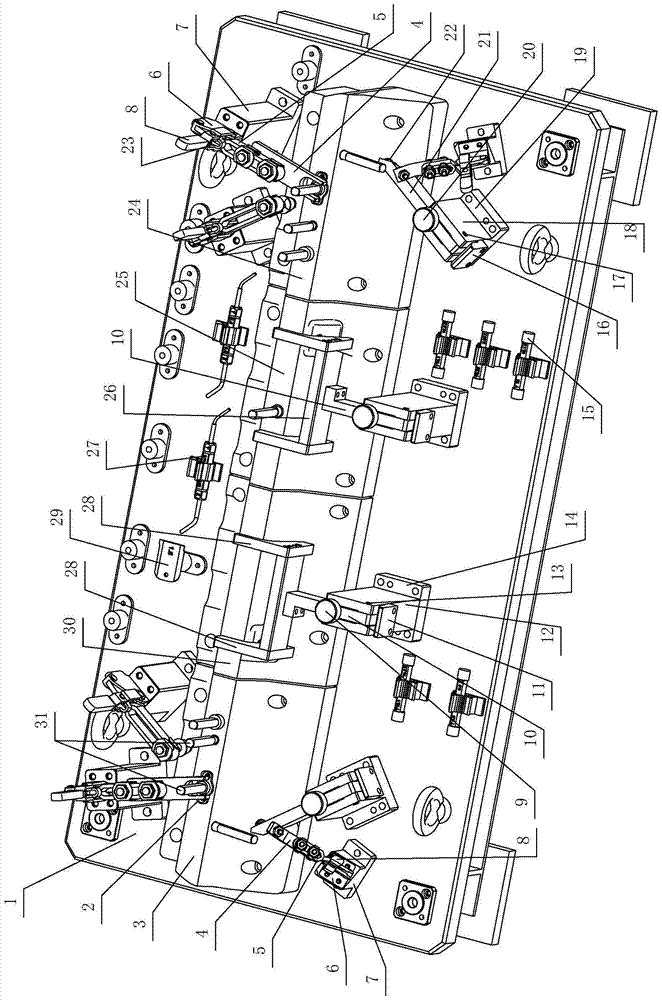
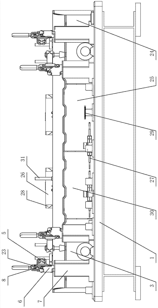
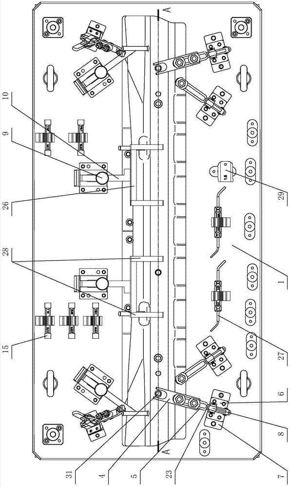
[0024] Depend on Figure 1 ~ Figure 4 It can be seen from the structural schematic diagram of the detection device of the automobile floor beam reinforcement of the present invention that it includes a bottom plate 1, a plurality of simulation blocks, a pressing device, a clamping device and a detection tool. The plurality of simulation blocks are sequentially connected to the base plate 1, and after the combination of the plurality of simulation blocks, the upper surface of the plurality of simulation blocks is the same in size as the surface shape of the automobile floor beam reinforcement 32, and the automobile floor beam reinforcement 32 is connected to The analog block is connected; the bottom end of the pressing device is connected with the base plate 1, and the upper end compresses the automobile floor beam reinforcement 32 wit...


PUM


Abstract

The invention discloses a detection device for an automobile floor beam reinforcement, which comprises a bottom plate (1), a plurality of simulation blocks, a pressing device, a clamping device and a detection tool; the multiple simulation blocks are sequentially connected to the bottom board (1) , and the upper surface of a plurality of simulation blocks is combined with the same surface shape and size as the automobile floor beam reinforcement (32), and the automobile floor beam reinforcement (32) is connected to the simulation block through a plurality of positioning pins (31); the pressing device The bottom end of the clamping device is connected to the base plate (1), and the upper end presses the automobile floor beam reinforcement (32) and the analog block; the bottom end of the clamping device is connected to the base plate (1), and the upper end is clamped with the analog block; the detection tool is connected to the base plate (1) plugging. After adopting this structure, in the testing process of a single product, it is guaranteed that the automotive floor beam reinforcement will not shift from beginning to end, thereby reducing the accumulated errors during testing and making the testing data more accurate.

Description

technical field [0001] The invention relates to the technical field of checking fixtures, in particular to a testing device for automobile floor beam reinforcements used for testing the degree of deformation of parts. Background technique [0002] The automobile floor beam is horizontally fixed on the bottom of the floor of the vehicle body, and its two ends are fixedly connected to the floor of the vehicle body. Therefore, the automobile floor beam is the supporting part of the car body. Whether it is a load-bearing body or a non-load-bearing body, the structure should meet the structural strength and rigidity, so as to ensure the load-carrying capacity of the body and meet the requirements of the body collision regulations. In the existing automobile floor beams, a reinforcing member is usually added to the beams to ensure the bearing capacity of the beams. However, on the one hand, this beam reinforcement itself is a long thin-walled strip part, which is prone to distort...

Claims


Application Information

Patent Timeline
Patent Type & Authority Patents(China)
IPC IPC(8): G01B5/00
Inventor 方煜定
Owner ZHEJIANG SHUNSHI AUTOMOBILE TECH
Why Eureka
Try Eureka