Retro-reflection grating scale measurement system and application thereof

A measurement system and grating ruler technology, applied in the direction of measuring devices, optical devices, instruments, etc., can solve the problem that the grating ruler measurement system cannot meet the application requirements of large vertical measurement range, and achieve the effect of high precision and stability

Inactive Publication Date: 2015-09-30
SHANGHAI MICRO ELECTRONICS EQUIP (GRP) CO LTD
View PDF6 Cites 23 Cited by
  • Summary
  • Abstract
  • Description
  • Claims
  • Application Information

AI Technical Summary

Problems solved by technology

[0008] The invention provides a retroreflective grating ruler measurement system and its application to solve the problem tha

Method used


Image

  • Retro-reflection grating scale measurement system and application thereof
  • Retro-reflection grating scale measurement system and application thereof
  • Retro-reflection grating scale measurement system and application thereof

Examples


Embodiment 1

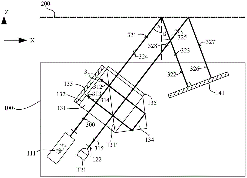
[0036] Preferably, please focus on the reference figure 2 , the retroreflection unit 140 is a mirror 141; the light source 110 is a dual-frequency laser light source 111; and the detector 121 is a single detector.

[0037]Preferably, the measurement unit 130 includes a polarization beamsplitter prism 131, a first quarter-wave plate 132, a second reflector 133, a corner cube prism 134 and a second quarter-wave plate 135, which are emitted from the light source 110 The light beam 300 is orthogonally polarized light with a certain frequency difference, including P-polarized light and S-polarized light. The surface 131' performs light splitting, and a part of the beam 311 (S polarized light) enters the second mirror 133 after passing through the first quarter-wave plate 132 (with a phase change of 90 degrees), and is captured by the second mirror 133, and pass through the first quarter-wave plate 132 again (phase change 180 degrees) of the light beam 312, at this time, the light...

Embodiment 2

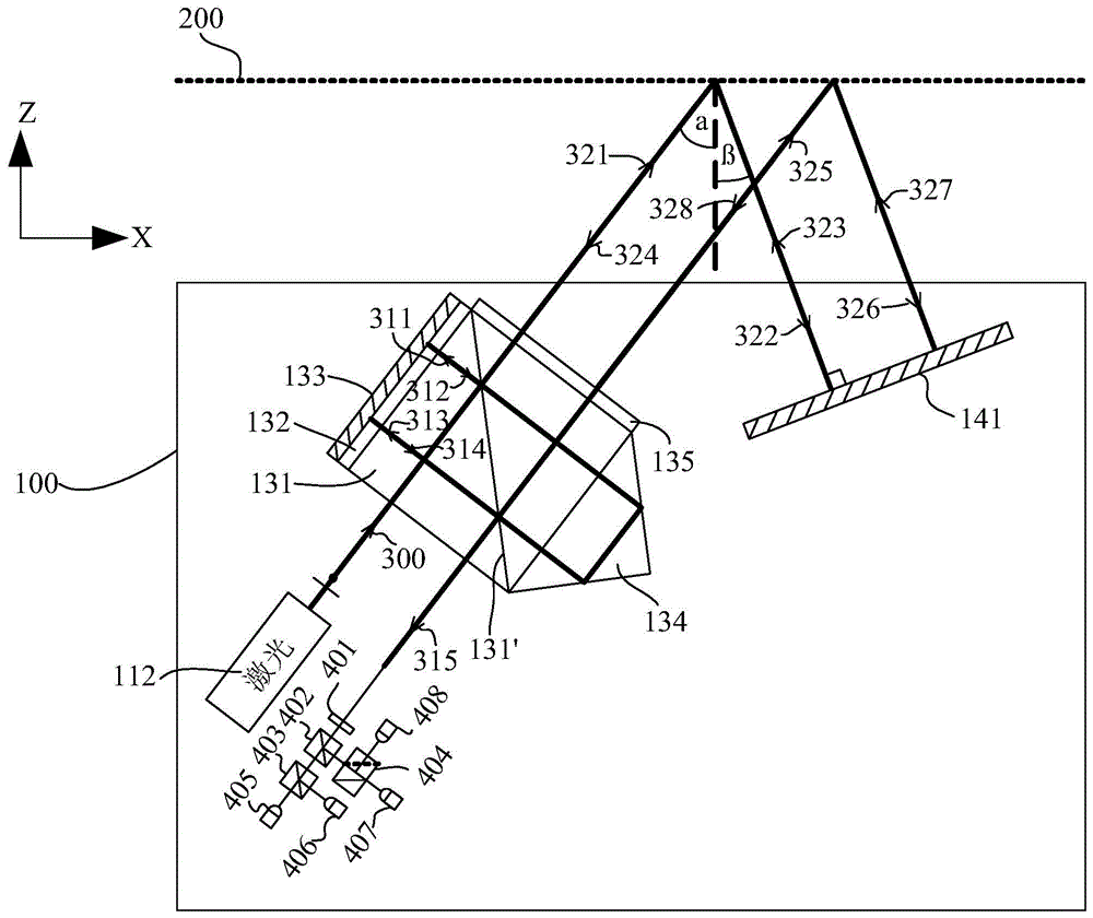
[0052] Please focus on reference Figure 7 The difference between this embodiment and Embodiment 1 is that the retroreflection unit 140 uses a reflective grating 142 .

[0053] Specifically, after the reference beam and the measuring beam pass through the polarizer, interference fringe signals are formed on the surface of the detector, and the number of interference fringes is obtained after photoelectric conversion, and the displacement information of the grating relative to the grating scale measuring probe 100 is calculated from this. The grating pitch of the grating 200 is d, and the wavelength of the laser light source is λ. According to the grating equation, d*(sinα+sinβ)=λ. Assuming that the grating 200 moves Δx in the X direction and Δz in the Z direction relative to the grating ruler measuring probe 100, the number N3 of stripes detected at the detector is:

[0054] N 3 + 2 Δx ...

Embodiment 3

[0066] Please focus on reference Figure 8 The difference between this embodiment and Embodiment 1 and Embodiment 2 is that the retroreflection unit 140 is in the form of a combination of a transmission grating 143 and a reflection mirror 144 .

[0067] Specifically, since the retroreflection unit 140 composed of the transmission grating 143 and the reflection mirror 144 in this embodiment has the same function as the reflection grating 142 in Embodiment 2, and the optical path structure is similar, the number of fringes detected at the detector can be Calculate according to formula (1-5).

[0068] With the structure in this embodiment, the data measured by the detector includes displacements in both the X direction and the Z direction. In order to separately obtain the displacements in the X direction and the Z direction, it is necessary to add a grating ruler detection head 100 to decouple the data of the two degrees of freedom. An additional grating ruler detection head 1...


PUM


Abstract

The invention relates to a retro-reflection grating scale measurement system and an application thereof. The system includes a grating scale measurement probe and a grating, wherein the grating scale measurement probe includes a light source, a signal output unit, a measurement unit and a retro-reflection unit. Light beams emitted by the light source enter the measurement unit and then strike on the grating in a non-Littrow angle after exiting the measurement unit. The light beams subjected to optical grating diffraction enter the retro-reflection unit and the light beams subjected to the retro-reflection of the retro-reflection unit return to the grating along the same optical path in the direction of the incident light. After being subjected to a second-time retro-reflection unit, the light beams return to the measurement unit along the same optical path. After being subjected to action of the measurement unit, the light beams enter the signal output unit and measurement signals are output from the signal output unit. The measurement system provided by the invention is less susceptible to environment during working and has a better repeated accuracy compared with an interferometer. At the same time, the measurement system can meet application requirements of a large vertical measurement range.

Description

technical field [0001] The invention relates to a retroreflective grating ruler measuring system and its application. Background technique [0002] Nano-measurement technology is the foundation of nano-processing, nano-manipulation, nano-materials and other fields. The IC industry, precision machinery, and micro-electromechanical systems all require high-resolution, high-precision displacement sensors to achieve nanometer-precision positioning. [0003] With the rapid development of integrated circuits in the direction of large-scale and high integration, the requirements for overlay accuracy of lithography machines are getting higher and higher. Correspondingly, the accuracy of obtaining six-degree-of-freedom position information of workpiece tables and mask tables also increased. [0004] The interferometer has a high measurement accuracy, which can reach the nanometer level. In the lithography system, it is used to measure the position of the workpiece stage and the mas...

Claims


Application Information

Patent Timeline
IPC IPC(8): G01B11/00
Inventor 吴萍张志平
Owner SHANGHAI MICRO ELECTRONICS EQUIP (GRP) CO LTD
Why Eureka
Try Eureka