Optical transparent frequency selecting surface structure and manufacturing method

A frequency selective surface, optically transparent technology, applied in the field of optical windows, can solve the problems of reducing light transmission performance, uneven energy distribution of high-order diffraction, uneven energy distribution, etc., and achieve the effect of improving light transmission performance

Active Publication Date: 2015-09-30
HARBIN INST OF TECH
View PDF7 Cites 24 Cited by
  • Summary
  • Abstract
  • Description
  • Claims
  • Application Information

AI Technical Summary

Problems solved by technology

[0011] In view of the above shortcomings and deficiencies, the present invention discloses an optically transparent frequency selective surface structure and a manufacturing method, which not only avoids the use of titanium dioxide solution, but also avoids the problem of reducing the light transmission performance of the optically transparent frequency selective surface structure due to the increase of the metal line width, And there is no need to use mechanical friction to remove the template, avoiding the traditional mechanical friction while reducing the light transmission performance and electromagnetic shielding performance of the optically transparent frequency selective surface structure, and also provides specific processing conditions that can solve the problem of uneven distribution of high-order diffraction energy. The optically transparent frequency selective surface structure produced by the method of the present invention not only has good electromagnetic shielding performance, but also achieves the effect of no obvious diffraction when solving the problem of uneven distribution of high-order diffraction energy, and has good light transmission performance

Method used


Image

  • Optical transparent frequency selecting surface structure and manufacturing method
  • Optical transparent frequency selecting surface structure and manufacturing method
  • Optical transparent frequency selecting surface structure and manufacturing method

Examples


specific Embodiment 1

[0051] This embodiment is an embodiment of an optically transparent frequency selective surface structure.

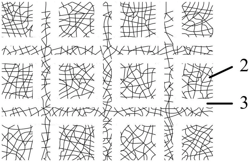
[0052] The optically transparent frequency selective surface structure of this embodiment includes a substrate 1, a transparent grid film 2 distributed on the substrate 1, and the surface of the transparent grid film 2 has a periodic opening array 3;

[0053] The shape of the transparent grid film 2 is a pattern formed by natural drying of cracked nail polish containing acrylic resin under the temperature of 20-25°C and humidity of 50-80%RH;

[0054] The inside of the periodic hole array 3 has one of the following two structures:

[0055] Structure 1, does not contain transparent grid film 2;

[0056] The second structure contains a transparent grid film 2, and the transparent grid film 2 inside the hole is not connected to the transparent grid film 2 outside the hole.

[0057] Here, the periodic hole array 3 is a square ring, the periodic hole array 3 contains a tran...

specific Embodiment 2

[0058] This embodiment is still an optically transparent frequency selective surface structure embodiment.

[0059] The optically transparent frequency selective surface structure of this embodiment includes a substrate 1, a transparent grid film 2 and a periodic hole array 3 distributed on the substrate 1; the transparent grid film 2 and the periodic hole array 3 are specifically The exchange of corresponding positions described in Embodiment 1.

specific Embodiment 3

[0060] This embodiment is an embodiment of a method for fabricating an optically transparent frequency selective surface structure.

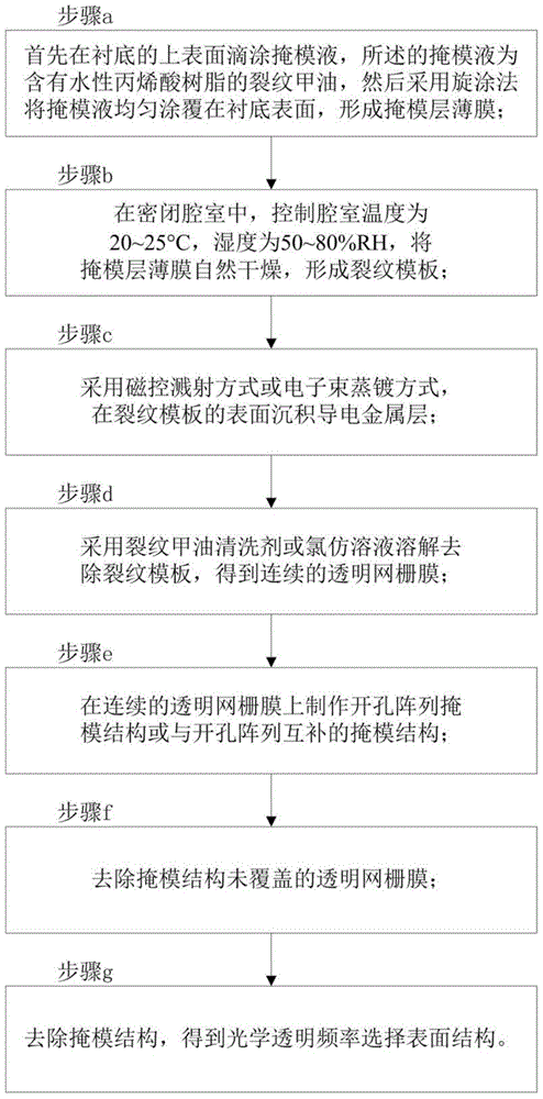
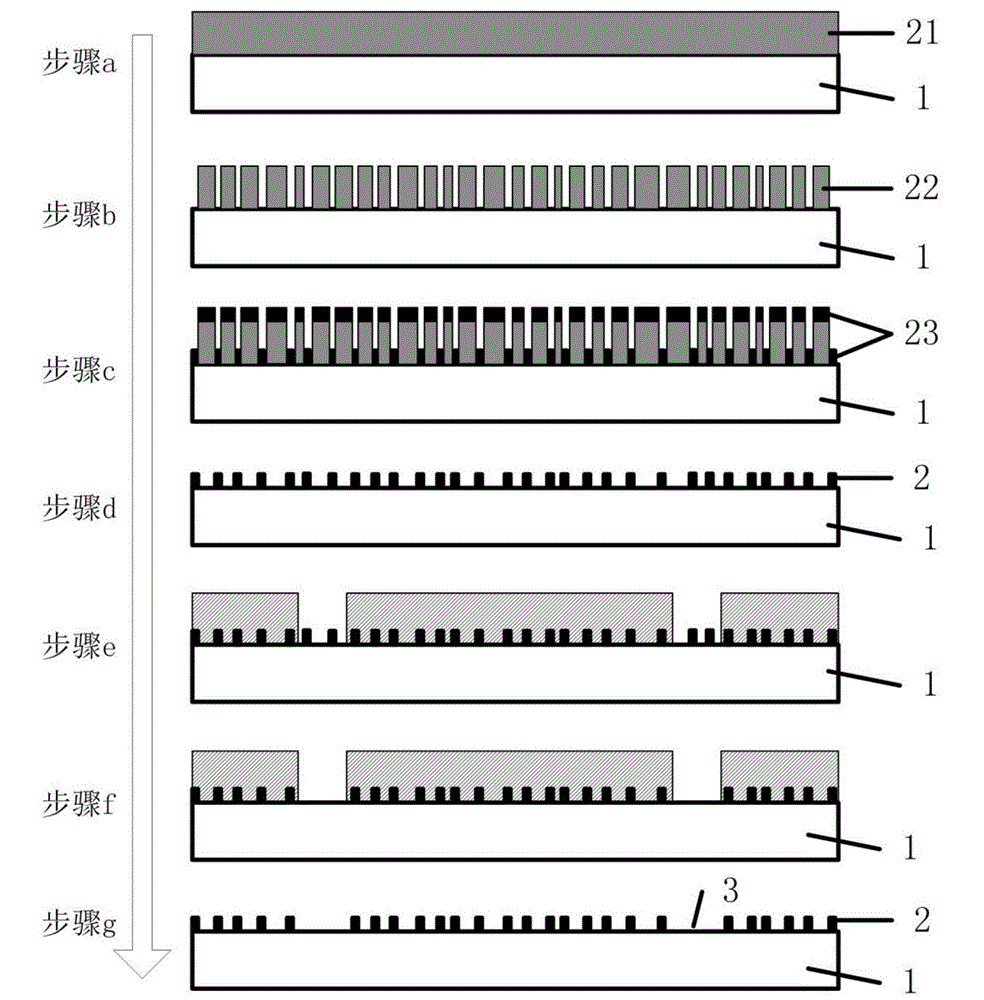
[0061] The manufacturing method of the optically transparent frequency selective surface structure of the present embodiment, the flow chart is as follows figure 2 shown. The method includes the following steps:

[0062] In step a, first drop-coat a masking liquid on the upper surface of the substrate 1, the masking liquid is cracked nail polish containing water-based acrylic resin, and then uniformly coat the masking liquid on the surface of the substrate 1 by a spin coating method , forming a mask layer film 21;

[0063] Step b, in a closed chamber, control the temperature of the chamber to 20-25° C. and the humidity to 50-80% RH, and dry the mask layer film 21 naturally to form the crack template 22;

[0064] Step c, using magnetron sputtering or electron beam evaporation to deposit a conductive metal layer 23 on the surface of the cracke...


PUM


Abstract

The invention provides an optical transparent frequency selecting surface structure and a manufacturing method, and belongs to the technical field of optical windows. The frequency selecting surface structure comprises a substrate and transparent mesh films which are distributed on the surface of the substrate and are provided with periodic hole arrays. The manufacturing method comprises the following steps of coating the upper surface of the substrate by using mask liquid; naturally drying the mask liquid to form a crack template under specific conditions; depositing a conductive metal layer on the surface of the crack template; removing the crack template to obtain the continuous transparent mesh films; manufacturing hole array mask structures or complementary structures thereof on the transparent mesh films; removing the transparent mesh films which are not wrapped by the mask structures; and removing the mask structures to obtain the optical transparent frequency selecting surface structure. By the optical transparent frequency selecting surface structure, the problem that the light transmittance performance of an optical window is reduced due to increasing of a metal line width is solved, the circumstance that the light transmittance performance and the electromagnetic shielding performance of the optical window are reduced simultaneously in the traditional mechanical friction mode is avoided, and specific processing conditions for solving the problem of non-uniform distribution of high-order diffraction energy are given.

Description

technical field [0001] An optically transparent frequency selective surface structure and a manufacturing method belong to the technical field of optical windows. Background technique [0002] Optical windows are widely used in telemetry and remote sensing, medical diagnosis, secure communication, aerospace equipment and other fields. Traditional optical windows are pure electromagnetic wave transmission windows. However, the continuous growth of electrical equipment will not only greatly increase the intensity of electromagnetic waves, but also broaden the wave band of electromagnetic waves, resulting in the deterioration of the space electromagnetic environment. Because traditional optical windows are transparent to electromagnetic waves, the deterioration of the electromagnetic environment May adversely affect electromagnetically sensitive equipment. In order to reduce electromagnetic interference, an electromagnetic shielding function needs to be added to the optical w...

Claims


Application Information

Patent Timeline
Patent Type & Authority Applications(China)
IPC IPC(8): G02B5/18H01P1/20
Inventor 韩余金鹏
Owner HARBIN INST OF TECH
Why Eureka
Try Eureka