
Original furnace roller surface roughness optimizing method in specific process segment of annealing machine

A technology of continuous retreat and optimization method, applied in special data processing applications, instruments, electrical digital data processing, etc., can solve problems such as buckling, wrinkling, and deviation

Inactive Publication Date: 2015-09-30
BAOSTEEL STAINLESS STEEL
View PDF0 Cites 11 Cited by
  • Summary
  • Abstract
  • Description
  • Claims
  • Application Information

AI Technical Summary

Problems solved by technology

On the spot, according to experience, the furnace rollers are constantly replaced to maintain the requirements for the roughness of the furnace rollers, so as to prevent the tension drop of the furnace section. However, the original surface roughness of the newly replaced furnace rollers is not a certain value, but a larger value. In this way, there are two problems in actual production: one is that when the original surface roughness reaches the upper limit of this range, on the one hand, the larger roughness is easy to cause buckling, which is not conducive to the stability of the plate On the other hand, when the furnace rolls still have the ability to use, the rolls are changed in advance, which increases the frequency of roll changes and seriously affects the production efficiency; second, when the original surface roughness is at the lower limit of this range, not only because Roughness is easy to cause deviation, and it is not conducive to the stability of the plate. Moreover, it may also cause production accidents such as strip deviation, edge rubbing, wrinkling, and strip breakage due to untimely change of rolls.

Method used


Image

  • Original furnace roller surface roughness optimizing method in specific process segment of annealing machine
  • Original furnace roller surface roughness optimizing method in specific process segment of annealing machine
  • Original furnace roller surface roughness optimizing method in specific process segment of annealing machine

Examples


Embodiment Construction

[0047] The specific implementation manners of the present invention will be described in detail below in conjunction with the accompanying drawings of the embodiments.

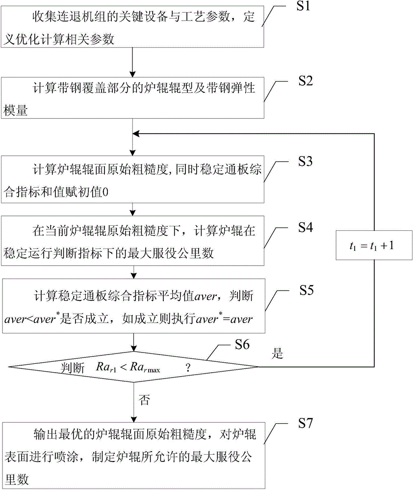
[0048] see figure 2 , figure 2 It is a flow chart of the method for optimizing the original roughness parameters of the furnace roll surface in the specific process section of the continuous annealing unit of the present invention, and the method for optimizing the original roughness parameters of the furnace roller surface in the specific process section of the continuous annealing unit of the present invention includes the following steps :

[0049] S1. Collect the key equipment and process parameters of the continuous annealing unit, and define the relevant parameters for optimization calculation;

[0050] The key equipment and process parameters of the continuous annealing unit include furnace roll profile parameters, strip steel parameters, and annealing process parameters in the heating section; the ...


PUM


Abstract

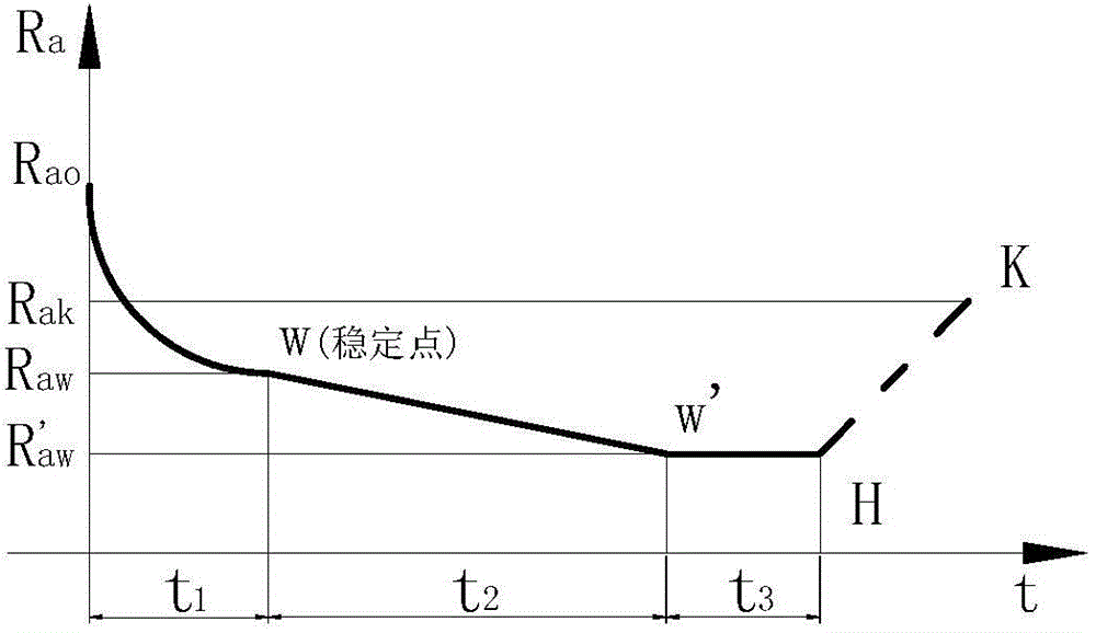
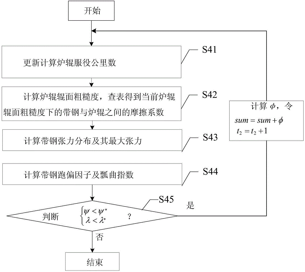
The invention discloses an original furnace roller surface roughness optimizing method in a specific process segment of an annealing machine. The method includes the steps that key equipment and process parameters of the annealing machine are collected; the furnace roller type and the elastic strip steel modulus of the strip steel covering part are calculated; traversal is conducted on the original furnace roller surface roughness within a certain value range, and the original furnace roller surface roughness with the minimum stable plate match aggregative indicator serves as the optimal value; spray coating is conducted on the furnace roller surface of the optimal original furnace roller surface roughness, and the maximum service mileage allowed by a furnace roller is made. Because the furnace roller surface roughness attenuation situation is fully considered, the purpose that the stable plate match performance of the strip steel keeps the best in the attenuation process of the furnace roller surface roughness serves as the target, and the optimized original furnace roller surface roughness value and the corresponding largest service mileage are determined, so that site production personnel can accurately master the furnace roller change time. The roller change frequency can be lowered, production efficiency is improved, and the stable plate match performance of the strip steel in the annealing machine is guaranteed.

Description

technical field [0001] The invention relates to the field of continuous annealing, in particular to an optimization method suitable for the original roughness of the furnace roll surface in a specific process section of a continuous annealing unit. Background technique [0002] In the cold rolling production process, the continuous annealing unit has gradually become an important part of the cold rolling production organization, and the equipment stability of the furnace section directly affects the operation of the continuous annealing unit. In the actual production process, the change of the surface roughness of the furnace roller in the furnace section is one of the focal issues for the smooth operation of the continuous annealing unit. In each process section of the continuous annealing unit furnace, in order to ensure that the friction coefficient of the roller surface can meet the strip tension maintenance of the continuous annealing unit furnace section, and improve t...

Claims


Application Information

Patent Timeline
IPC IPC(8): G06F19/00
Inventor 段建高刘益龙何中炜李辉庭陆子凡王亮武胜林
Owner BAOSTEEL STAINLESS STEEL
Learn More