Photo management method and system
A management system and photo technology, applied in the field of telecommunication, can solve the problem of low efficiency of photo classification, search and identification
- Summary
- Abstract
- Description
- Claims
- Application Information
AI Technical Summary
Problems solved by technology
Method used
Image
Examples
Embodiment 1
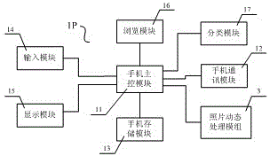
[0096] like image 3 As shown, this embodiment is a mobile phone terminal 1P, which includes a mobile phone main control module 11, a mobile phone communication module 12, a mobile phone storage module 13, an input module 14, a display module 15, a browsing module 16, a classification module 17 and photo dynamics. The processing module 3 and the main control module 11 of the mobile phone are connected with each functional module.
[0097] like image 3 As shown, the user inputs a photo browsing command from the input module 14 to the main control module 11 of the mobile phone, and the main control module 11 of the mobile phone starts the browsing module 16 according to the received photo browsing command, obtains corresponding photo data from the mobile phone storage module 13 and displays them on the display module 15 display, or classify and store photos through the classification module 17.
[0098] like image 3 As shown, the user provides filtering conditions by the in...
Embodiment 2
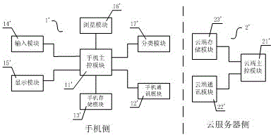
[0125] like Figure 7 As shown, this embodiment includes a cloud server 2 and a mobile phone terminal 1, wherein the mobile phone terminal 1 includes a mobile phone main control module 11, a mobile phone communication module 12, a mobile phone storage module 13, an input module 14, a display module 15, and a browsing module 16 , a classification module 17, the main control module 11 is connected with the communication module 12, the storage module 13, the input module 14, the display module 15, the browsing module 16 and the classification module 17.
[0126] like Figure 7 As shown, the cloud server 2 includes a cloud main control module 21, a cloud communication module 22, a cloud storage module 23, and a photo dynamic processing module 3. The cloud main control module 21, the cloud communication module 22, the cloud storage module 23, and the photo dynamic processing module Group 3 is connected.
[0127] like Figure 7 As shown, the mobile phone communication module 12 a...
Embodiment 3
[0175] like Figure 11 As shown, this embodiment includes a cloud server 2 and N mobile terminals (namely, mobile terminal a1, mobile terminal a2, ..., mobile terminal aN), forming a combined remote processing system. The big difference between this embodiment and Embodiment 2 is that: N mobile phone terminals are registered on the cloud server 2, so that it is possible for the cloud server 2 to identify the names of multiple people in the tag library 37 (that is, their respective user names ). For example, if everyone in a family has uploaded a sample photo, each person's name (ie, their respective user names) can be identified for the group photo of the family.
[0176] As for other specific structures and control procedures, which are the same or similar to those in Embodiment 2, details will not be repeated here.
PUM
 Abstract
Description
Claims
Application Information
 - R&D
- Intellectual Property
- Life Sciences
- Materials
- Tech Scout
- Unparalleled Data Quality
- Higher Quality Content
- 60% Fewer Hallucinations
Browse by: Latest US Patents, China's latest patents, Technical Efficacy Thesaurus, Application Domain, Technology Topic, Popular Technical Reports.
© 2025 PatSnap. All rights reserved.Legal|Privacy policy|Modern Slavery Act Transparency Statement|Sitemap|About US| Contact US: help@patsnap.com


