Coil unit and wireless transmission device

一种无线电力传输、线圈单元的技术,应用在电路装置、电池电路装置、电力牵引等方向,能够解决电子仪器不良影响、漏磁场、漏磁场强度变高等问题,达到抑制磁耦合变得过高、抑制电力传输效率的下降、减小漏磁场的效果

Active Publication Date: 2015-09-30
TDK CORPARATION
View PDF7 Cites 8 Cited by
  • Summary
  • Abstract
  • Description
  • Claims
  • Application Information

AI Technical Summary

Problems solved by technology

However, when a coil is helically wound on a magnetic core, a magnetic flux is easily generated to go around a place away from the coil, so there is a problem that an unnecessary leakage magnetic field is likely to be formed at a place away from the coil.
Especially when the wireless power transmission technology is applied to the charging device in power electronic equipment such as electric vehicles, due to the requirement of large power transmission, a large current needs to flow through the coil, so the strength of the leakage magnetic field formed at a place far away from the coil will also increase. There is concern about causing electromagnetic wave disturbances and causing adverse effects on surrounding electronic devices, etc.

Method used


Image

  • Coil unit and wireless transmission device
  • Coil unit and wireless transmission device
  • Coil unit and wireless transmission device

Examples


no. 1 Embodiment approach

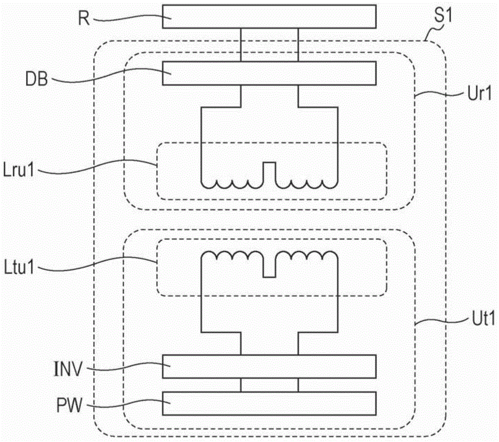
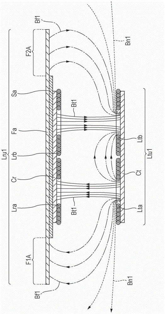
[0028] First, refer to figure 1 as well as figure 2 The overall configuration of the wireless power transmission device S1 according to the first embodiment of the present invention will be described. In addition, in this embodiment, an example in which the coil unit according to the present invention is applied to a power receiving coil unit in a wireless power transmission device will be described. figure 1 It is a system configuration diagram showing the wireless power transmission device according to the first embodiment of the present invention together with loads. figure 2 It is a schematic cross-sectional view showing a power transmitting coil unit and a power receiving coil unit in the wireless power transmission device according to the first embodiment of the present invention. in addition, figure 2 2 schematically shows the magnetic fluxes generated by the first and second power transmission coils Lta and Ltb, and omits the magnetic cores Ct and Cr of the power...

no. 2 Embodiment approach

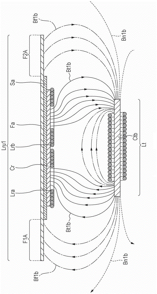
[0057] Next, refer to image 3 The wireless power transmission device S1b according to the second embodiment of the present invention will be described. image 3 This is a diagram schematically showing magnetic flux generated by the power transmission coil in a cross-sectional view showing the power reception coil unit according to the second embodiment of the present invention together with the power transmission coil. However, in this figure, the magnetic flux generated by the power transmission coil Lt is schematically shown, and the diagram of the magnetic flux in the power transmission coil Lt and the magnetic cores Ctb, Cr, and magnetic body Fa of the power reception coil unit Lru1 is omitted. Show. and also, image 3 Among the magnetic flux generated by the power transmission coil Lt, the magnetic flux Bt1b interlinked with the first and second power reception coils Lra and Lrb is shown as a representative magnetic flux, and the large circle circles away from the powe...

no. 3 Embodiment approach

[0069] Next, refer to Figure 4 The wireless power transmission device S2 according to the third embodiment of the present invention will be described. In addition, in this embodiment, an example in which the coil unit according to the present invention is applied to a power transmission coil unit in a wireless power transmission device will be described. Figure 4 It is a diagram schematically showing magnetic fluxes generated by the first and second power transmission coils in a cross-sectional view showing the power transmission coil unit and the power reception coil according to the third embodiment of the present invention. However, illustration of the magnetic fluxes in the magnetic cores Ct, Cr and the magnetic body Fb of the power transmitting coil unit Ltu2 and the power receiving coil unit Lru2 is omitted in this figure. and also, Figure 4 Among the magnetic fluxes generated by the first and second power transmitting coils Lta and Ltb, the magnetic flux Bt2 interl...


PUM


Abstract

A coil unit includes a non-magnetic conductive plate which is disposed in an arrangement direction of first and second coils have reverse winding direction to each other, and a magnetic body. The magnetic body includes a first portion which is positioned in an outer side than an outline of one side of the conductive plate in the arrangement direction of the first and second coils, and a second portion which is positioned in an outer side than an outline of the other side of the conductive plate in the arrangement direction of the first and second coils. When viewing from the arrangement direction of the first and second coils, the first and second portions are positioned on a side of the conductive plate where is opposite to a side which faces the first and second coils.

Description

technical field [0001] The invention relates to a coil unit and a wireless power transmission device. Background technique [0002] In recent years, in order to supply power without mechanical contact such as cables, the wireless power transmission technology that utilizes the electromagnetic induction between the primary (power transmission) coil and the secondary (power reception) coil facing each other has attracted people's attention. attention, it is predicted that it will be widely used as a power feeding device for charging secondary batteries mounted on electric vehicles (EV: Electric Vehicle) and plug-in hybrid electric vehicles (PHEV: Plug-in Hybrid Electric Vehicle) use. [0003] However, when wireless power transmission technology is applied as a power feeding device that feeds electric power to electric vehicles, etc., it is conceivable that the positional relationship between the power transmission coil installed on the ground, etc., and the power reception co...

Claims


Application Information

Patent Timeline
Patent Type & Authority Applications(China)
IPC IPC(8): H01F38/14H02J7/02H02J17/00
CPCH02J5/005H02J7/025H01F38/14H01F27/34B60L2210/30B60L2210/40B60L11/1824H01F27/365H01F27/288B60L2240/36H01F27/346B60L11/182Y02T90/12Y02T10/7072Y02T90/14B60L53/30H02J50/10H02J50/70B60L53/122B60L53/126H01F27/36Y02T10/70Y02T10/72H01F27/363
Inventor 千代宪隆西山哲哉寺崎泰弘铃木满成
Owner TDK CORPARATION
Why Eureka
Try Eureka