Laser generator

A laser generator, laser wavelength technology, used in lasers, phonon exciters, laser parts, etc., to achieve the effects of high work efficiency, fine cutting lines, and stable performance

Inactive Publication Date: 2015-09-30
张家港市旭华激光有限公司
View PDF6 Cites 4 Cited by
  • Summary
  • Abstract
  • Description
  • Claims
  • Application Information

AI Technical Summary

Problems solved by technology

[0004] The technical problem mainly solved by the present invention is to reduce the waste of energy in the conversion of laser light to thermal energy, and to provide high-quality, high-density laser beams. The laser generator of the present inv

Method used


Image

  • Laser generator

Examples


Embodiment Construction

[0017] The preferred embodiments of the present invention will be described in detail below in conjunction with the accompanying drawings, so that the advantages and features of the present invention can be more easily understood by those skilled in the art, so as to define the protection scope of the present invention more clearly.

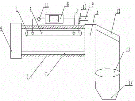
[0018] see figure 1 , the embodiment of the present invention includes:

[0019] The laser generator described above includes a discharge tube. The gas chamber in the discharge tube is provided in the discharge tube. The gas cavity in the discharge tube is filled with mixed gases such as CO2, N2, and HE. Two discharge tubes are arranged at both ends of the discharge tube. The tube electrode, the two discharge tube electrodes are connected to the power supply through wires, and a controller is set between the power supply and the discharge tube electrodes. The controller is used to control the switch of the power supply to realize the pressurizati...


PUM

PropertyMeasurementUnit
Laser wavelengthaaaaaaaaaa
Poweraaaaaaaaaa

Abstract

The invention discloses a laser generator. The laser generator comprises a discharge tube, an internal discharge pipe gas cavity is arranged in the discharge tube and is filled with mixed gas of CO2, N2, HE and the like, two discharge tube electrodes are arranged at two ends of the discharge tube and are connected with a power source via leads, and a controller is arranged between the power source and the discharge tube electrodes.

Description

technical field [0001] The invention relates to the field of laser equipment, in particular to a laser generator. Background technique [0002] With the development of optoelectronic integration technology, the application of laser is more and more extensive. In the application of precision machinery, laser operation has a strong advantage. Laser belongs to non-contact processing, and it is local processing without mechanical extrusion. [0003] Now there are professional laser welding machines, laser cutting machines, laser marking machines, and drilling machines, which use focusing mirrors to focus the laser beam on the surface of the material to melt the surface material, and at the same time compress the gas to blow away the melted material. In laser equipment During use, the laser generator provides the energy source for the laser equipment and is the most important part of the laser equipment. Most of the existing laser generators use solid-state laser generators, whic...

Claims


Application Information

Patent Timeline
IPC IPC(8): H01S3/223H01S3/038H01S3/034
Inventor 孟燕
Owner 张家港市旭华激光有限公司
Why Eureka
Try Eureka