All-magnetic power machine with electromagnetic pulse flux control device

A technology of electromagnetic pulse and magnetic flux, applied in the direction of electromechanical devices, generators/motors, electric components, etc., which can solve the problems of heavy overall mass, limited use range, and short service period.

Inactive Publication Date: 2015-09-30
章宪
View PDF0 Cites 0 Cited by
  • Summary
  • Abstract
  • Description
  • Claims
  • Application Information

AI Technical Summary

Problems solved by technology

[0002] At present, the development of equipment that converts the magnetic energy of rare earth NdFeB alloy super permanent magnets into mechanical energy is very urgent. During the development process, new technical problems will continue to be discovered in the entire application system, such as: using rare earth for the rotor and stator of the motor The permanent magnet becomes an all-magnetic power machine, but which method is the most suitable to break the balance of the constant magnetic field? The traditional motor uses a large-capacity battery pack for charging and discharging, and needs to be equipped with a large number of batteries, resulting in a heavy overall quality, and the battery pack has a short service life after being fully charged each time, and requires frequent charging, which limits the scope of use. How to find a way to extend the use Cycle method? The above problems can be explored from the way of traditional motor work to explore innovative methods, and make new technological inventions and innovative solutions

Method used


Image

  • All-magnetic power machine with electromagnetic pulse flux control device
  • All-magnetic power machine with electromagnetic pulse flux control device
  • All-magnetic power machine with electromagnetic pulse flux control device

Examples


example 2

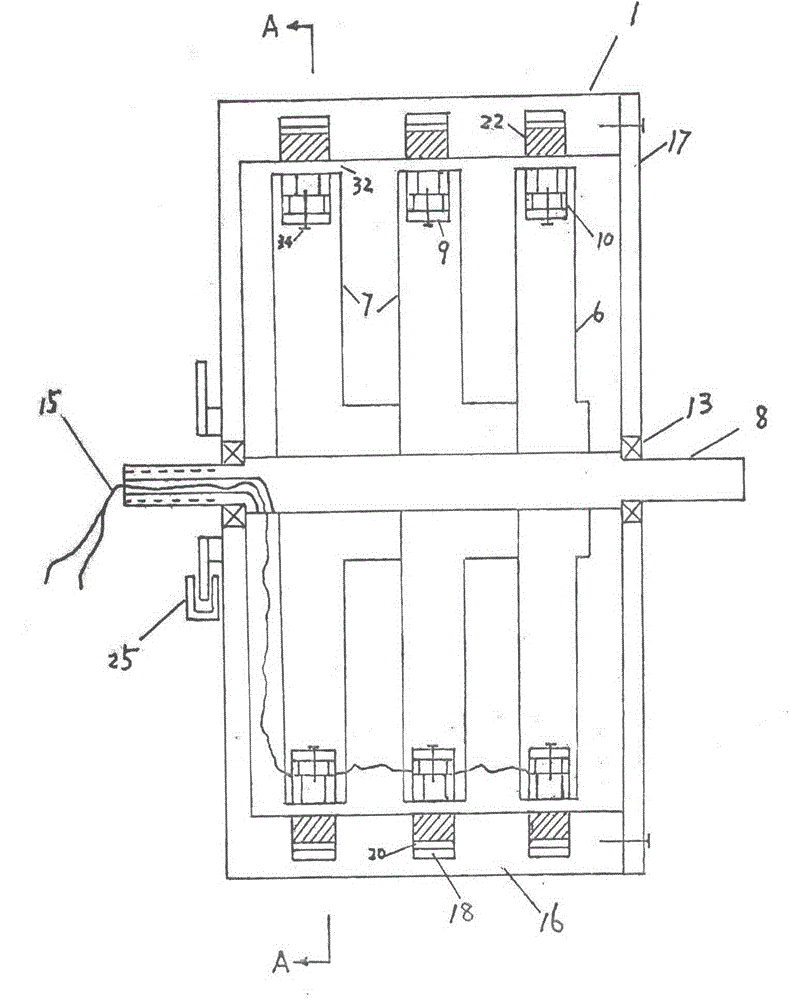
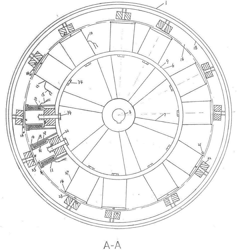
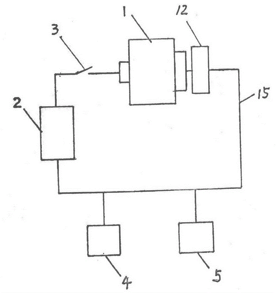
[0017]Example 2: For another type of shell fixed and rotating inner pivot type full magnetic power machine 1 with an electromagnetic pulse regulating magnetic flux device, including a turntable 16, a fixed shell 33, an electromagnetic pulse programming controller 2, a composite magnetic head A10, and a composite magnetic head B11 , operating switch 4, storage and discharge energy assembly 5, several turntables 16 are installed on the main shaft 8 of the turntable 16, and permanent magnets 22 and turntable iron rings 18 are installed on each turntable 16 to form closed magnets on several turntables 16. The other magnetic pole of the rotating disk iron ring 18 on each rotating disk 16 is connected with the permanent magnet 22 and the composite magnetic head A10 and the composite magnetic head B11 on the fixed casing 33 are correspondingly dynamically grouped, and the stator iron ring 9 on the fixed casing 33 is connected with several One end of composite magnetic head A10, compos...


PUM


Abstract

The invention relates to an all-magnetic power machine with an electromagnetic pulse flux control device. The all-magnetic power machine adopts a rotating outer casing and inner stator type or a fixed outer casing and rotating inner pivot type; the all-magnetic power machine comprises the stator, turntables, an electromagnetic induction pulse programming governor, composite heads, a power generator, a speed regulator and an electric energy storage component; a closed magnetic circuit formed by combination of a plurality of permanent magnets and stator iron rings is mounted on the surface of a stator, and the U-shaped composite heads are mounted on the stator iron rings; the electric energy storage component is used for supplying electricity, so that after the all-magnetic power machine is started, the power generator works to charge the electric energy storage component; in the working process of the power generator, controllable induced pulse electromagnetic fields are generated by a pulse regulator to play a variable magnetism role; the generated electromagnetic fields have a stacking disturbing phenomenon to reduce the magnetic resistance; smooth continuous rotating of the permanent magnets correspondingly mounted on the turntables under the action of magnetic energy acting force is facilitated; the electric energy storage component needs to be supplemented with electricity in time according to an electric quantity indicator light; the use time of the electric energy storage component after being charged fully each time is prolonged; the quantity of traditional storage batteries can be reduced. The all-magnetic power machine is an environmental-friendly new renewable energy resource.

Description

technical field [0001] The invention relates to the technical field of a rare earth permanent magnet application system for converting magnetic energy into mechanical energy. Background technique [0002] At present, the development of equipment that converts the magnetic energy of rare earth NdFeB alloy super permanent magnets into mechanical energy is very urgent. During the development process, new technical problems will continue to be discovered in the entire application system, such as: using rare earth for the rotor and stator of the motor The permanent magnet becomes an all-magnetic power machine, but which method is the most suitable to break the balance of the constant magnetic field? The traditional motor uses a large-capacity battery pack for charging and discharging, and needs to be equipped with a large number of batteries, resulting in a heavy overall quality, and the battery pack has a short service life after being fully charged each time, and requires frequ...

Claims


Application Information

Patent Timeline
Patent Type & Authority Applications(China)
IPC IPC(8): H02N11/00H02K53/00
CPCH02K53/00H02K99/20H02K1/17H02K1/18H02K1/278H02K25/00H02P7/282
Inventor 章宪章文婕朱小燕
Owner 章宪
Why Eureka
Try Eureka