
Intelligent illumination control system

A technology of intelligent lighting control and data control, which is applied in the direction of energy-saving control technology, lighting devices, light sources, etc., can solve the problem that the brightness and power consumption of lighting lamps are not well adjusted, the wiring work and installation work are cumbersome, and the total cost of equipment Advanced problems, to achieve the effect of reducing lighting power consumption, improving efficiency and prolonging service life

Inactive Publication Date: 2015-09-30
GUANGXI UNIV
View PDF4 Cites 1 Cited by
  • Summary
  • Abstract
  • Description
  • Claims
  • Application Information

AI Technical Summary

Problems solved by technology

[0002] In many public places, such as schools, hospitals, office buildings, shopping malls, hotels, bars, etc., these public places and corridors are installed with independent lighting, emergency lights, fire detection devices and alarm devices, video surveillance cameras, etc., lighting The function of the light is to provide daily lighting in the mains power supply network. The function of the emergency light is to use the electric energy stored in the battery to provide emergency lighting after a power failure. The function of the fire detection device and the alarm device is to enable people to Immediately know that the people on the scene can deal with or evacuate in time, and the staff of the monitoring center can take rescue measures in time to ensure the safety of people's lives and property. At the same time, install lighting, emergency lights, fire detection circuits and alarm circuits in corridors and corridors. Video surveillance cameras, etc., on the one hand, need to lay a large number of lines, and the wiring work and installation work are relatively cumbersome. On the other hand, these devices need to be purchased separately, and the total cost of the equipment is also high. and power consumption are not well modulated, resulting in a large amount of power consumption

Method used


Image

  • Intelligent illumination control system

Examples


Embodiment Construction

[0015] The technical solutions in the embodiments of the present invention will be clearly and completely described below in conjunction with the accompanying drawings in the examples of the present invention. Obviously, the described embodiments are only some of the embodiments of the present invention, not all of them. Based on the embodiments of the invention, all other embodiments obtained by persons of ordinary skill in the art without creative efforts fall within the protection scope of the present invention.

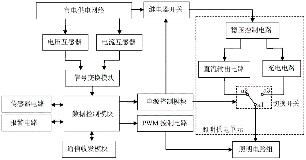
[0016] Such as figure 1 As shown, an intelligent lighting control system includes a data control module, a voltage transformer, a current transformer, a signal conversion module, a power control module, a relay switch, a PWM control circuit, a lighting circuit group, and a lighting power supply unit. The modules are respectively connected to the signal transformation module, the power supply control module and the PWM control circuit. The voltage transformer and t...


PUM


Abstract

The invention belongs to the technical field of LED illumination control, and particularly relates to an intelligent illumination control system. The system comprises a data control module, a voltage transformer, a current transformer, a signal transformation module, a power supply control module, a relay switch, a PWM (pulse-width modulation) control circuit, an illumination circuit group and an illumination power supply unit, wherein the data control module is connected with the signal transformation module, the power supply control module and the PWM control circuit respectively; the voltage transformer and the current transformer are connected with the signal transformation module respectively. The intelligent illumination control system can monitor the power condition of a main supply network in real time and can regulate the brightness of an LED lamp assembly according to electricity consumption in a line, accordingly, the consumption of illumination electric energy is reduced, and the service life of an LED lamp is prolonged.

Description

technical field [0001] The invention belongs to the technical field of LED lighting control, and in particular relates to an intelligent lighting control system. Background technique [0002] In many public places, such as schools, hospitals, office buildings, shopping malls, hotels, bars, etc., these public places and corridors are installed with independent lighting, emergency lights, fire detection devices and alarm devices, video surveillance cameras, etc., lighting The function of the light is to provide daily lighting in the mains power supply network. The function of the emergency light is to use the electric energy stored in the battery to provide emergency lighting after a power failure. The function of the fire detection device and the alarm device is to enable people to Immediately know that the people on the scene can deal with or evacuate in time, and the staff of the monitoring center can take rescue measures in time to ensure the safety of people's lives and p...

Claims


Application Information

Patent Timeline
IPC IPC(8): H05B37/02
CPCY02B20/40
Inventor 桑川川
Owner GUANGXI UNIV
Learn More