Exhaust purification device

An exhaust purification device and catalyst technology, which is applied to exhaust devices, exhaust treatment, noise reduction devices, etc., can solve the problem of low coal dust removal, and achieve the effect of efficient removal and inhibition of coal dust adhesion.

Inactive Publication Date: 2015-09-30
YANMAR CO LTD +1
View PDF6 Cites 0 Cited by
  • Summary
  • Abstract
  • Description
  • Claims
  • Application Information

AI Technical Summary

Problems solved by technology

Therefore, due to the NO x The catalyst also injects pressurized air, so the problem is that the amount of soot removal corresponding to the air consumption becomes low, and soot cannot be removed efficiently

Method used


Image

  • Exhaust purification device
  • Exhaust purification device
  • Exhaust purification device

Examples


Embodiment Construction

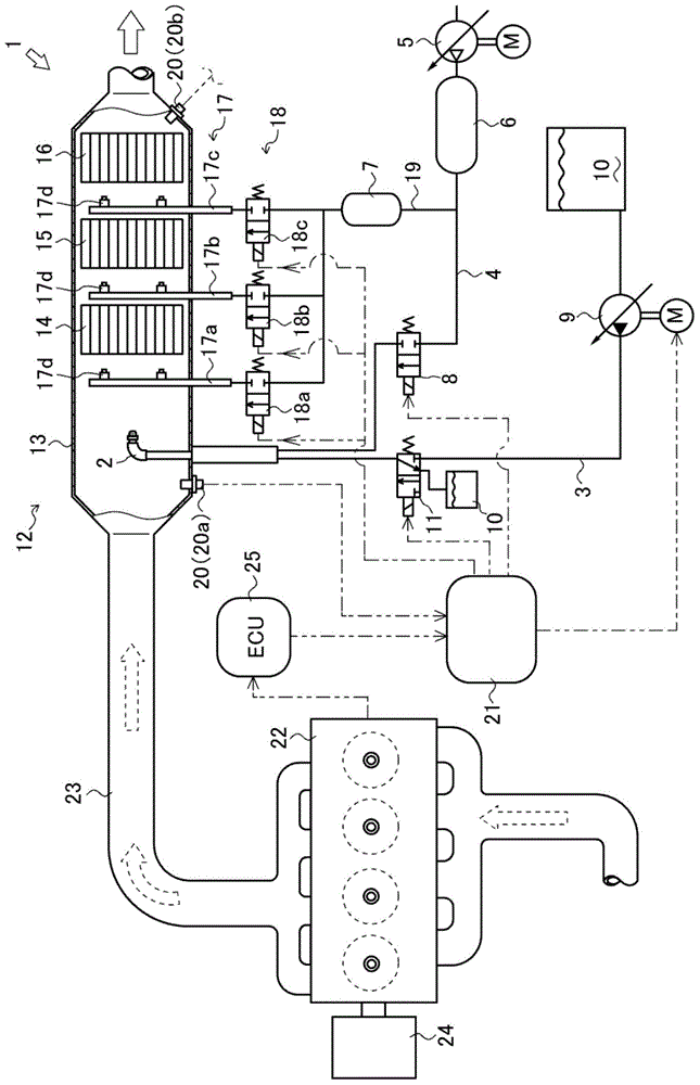
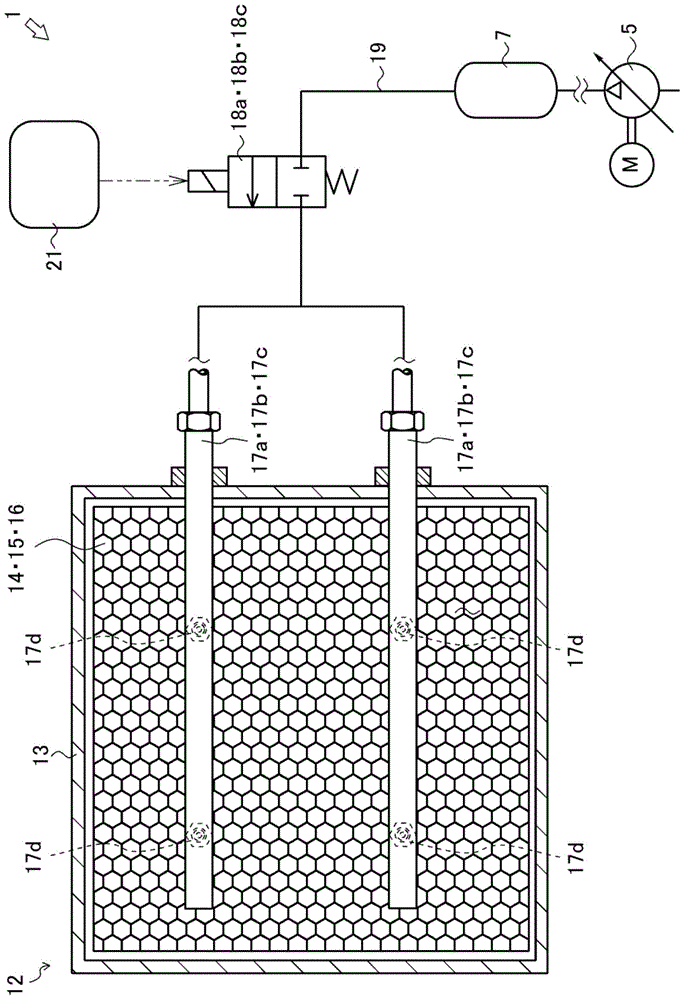
[0033] Below, use figure 1 as well as figure 2 , the exhaust gas purification device 1 which is the first embodiment of the exhaust gas purification device of the present invention will be described. In addition, the "upstream side" in this embodiment means the upstream side in the fluid flow direction, and the "downstream side" means the downstream side in the fluid flow direction. In addition, the exhaust device is not limited to this embodiment, and may be an airless system that does not use pressurized air.

[0034] Such as figure 1 As shown, the exhaust purification device 1 is a device for purifying exhaust gas discharged from an engine 22 which is an internal combustion engine that drives an electric generator 24 . The exhaust purification device 1 is provided in an exhaust pipe 23 of an engine 22 . The exhaust purification device 1 includes: urea water injection nozzle 2, urea supply flow path 3, first air supply flow path 4, pressurized air supply pump (compresso...


PUM


Abstract

The purpose of the present invention is to provide an exhaust purification device capable of efficiently performing removal of dust and soot adhering to NOx catalysts and limiting dust and soot adhesion. An exhaust purification device (1) in which a catalytic reactor (12) comprising multiple catalysts, a first NOx catalyst (14), a second NOx catalyst (15) and a third NOx catalyst (16), disposed side by side in the direction of exhaust flow, is provided with a first soot blower (17a), a second soot blower (17b) and a third soot blower (17c) for jetting pressurized air to remove dust and soot adhering to the first NOx catalyst (14), the second NOx catalyst (15) and the third NOx catalyst (16). The exhaust purification device is configured so that a soot blower is disposed at each catalyst and, of the respective jetted air volumes jetted from the first soot blower (17a), the second soot blower (17b) and the third soot blower (17c) during a constant period, the jetted air volume jetted from the first soot blower (17a) of the first NOx catalyst (14), which is disposed the most upstream, is the highest.

Description

technical field [0001] The invention relates to an exhaust purification device of an internal combustion engine. Background technique [0002] Conventionally, there is known an exhaust purification device which reduces NO contained in exhaust gas from an internal combustion engine. x (nitrogen oxides), using NO x Catalyst reactor (SCR catalyst) and ammonia as reducing agent, NO x Reduced to nitrogen and water. The exhaust purification device generates ammonia gas from urea water injected into high-temperature exhaust gas, and makes it combine with NO x Catalyst contact, thus the NO x Reduced to nitrogen and water. [0003] In such an exhaust purification device, the NO in the catalytic reactor x As the catalyst, a catalyst having a honeycomb structure having many through-holes is used as an active component material such as V and Cr contained in a carrier of an oxide such as Ti. With this structure, the contact area is increased and the reduction reaction is promoted....

Claims


Application Information

Patent Timeline
IPC IPC(8): B01D53/86F01N3/20F01N3/24
CPCF01N2610/02B01D53/96F01N3/208F01N2610/085F01N13/0097Y02T10/24B01D53/9431F01N13/0093F01N2610/146Y02T10/12
Inventor 井上刚
Owner YANMAR CO LTD
Why Eureka
Try Eureka