Super sand mill with double-separation system

A technology of separation system and sand mill, which is applied in the direction of grain processing, etc., can solve the problems of grinding medium blockage, short service life, low separation efficiency, etc., and achieve the effect of avoiding material blockage or no output, and speeding up the output speed

Inactive Publication Date: 2015-10-07
PUHLER GUANGDONG SMART NANO TECH CO LTD
View PDF9 Cites 18 Cited by
  • Summary
  • Abstract
  • Description
  • Claims
  • Application Information

AI Technical Summary

Problems solved by technology

The screen of the existing sand mill discharge separation system adopts a gap type separation system, which directly separates the material and the grinding medium, not only the separation effect is poor, but also the separation efficiency is low
Most of them are cylindrical or drum-shaped, and there are generally two kinds of sieve holes formed between the sieve bars, one with a rectangular cross-section.

Method used


Image

  • Super sand mill with double-separation system
  • Super sand mill with double-separation system
  • Super sand mill with double-separation system

Examples


Embodiment Construction

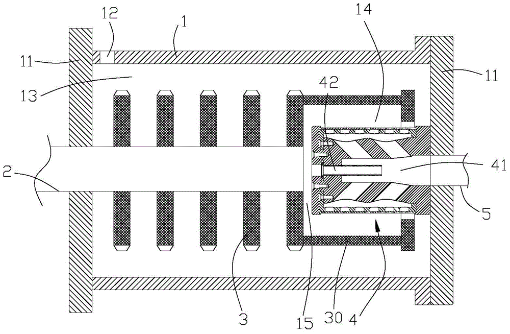
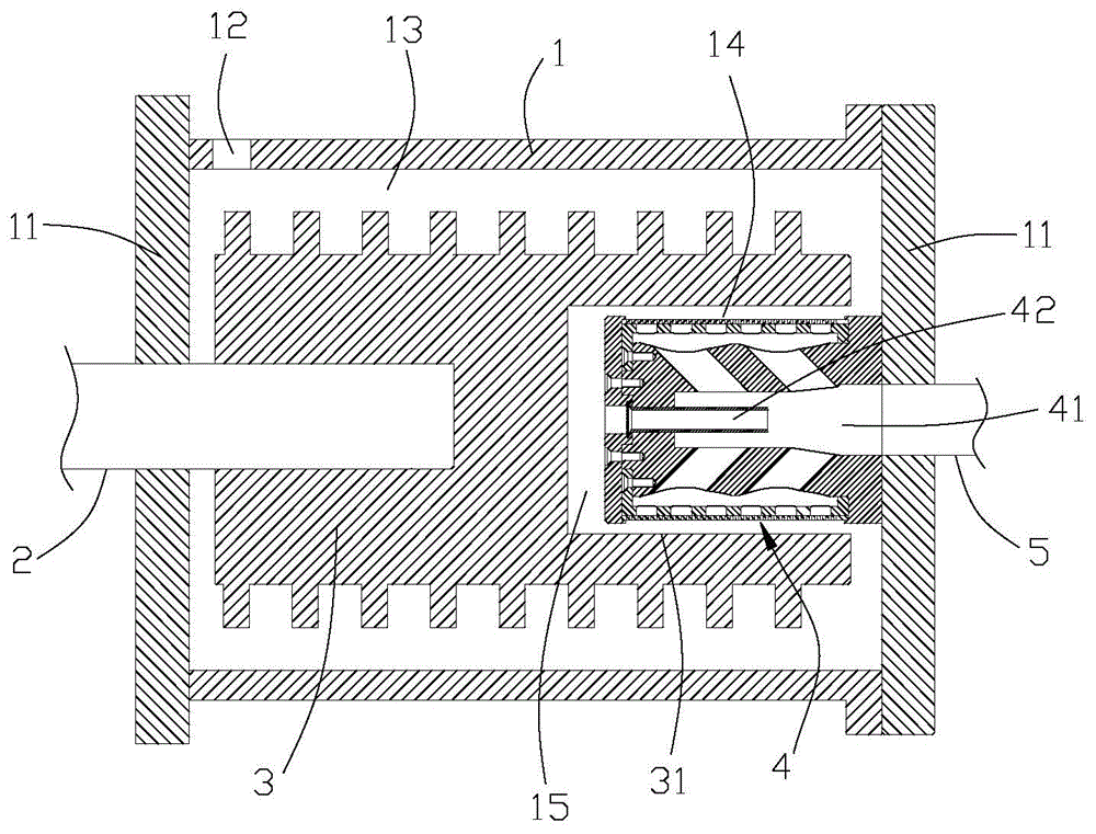
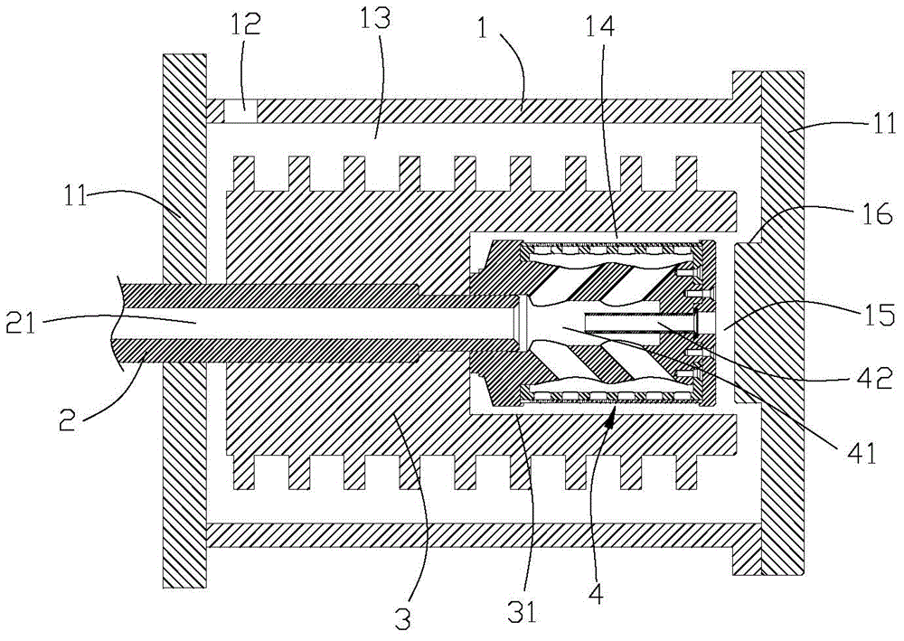
[0023] The super sand mill with double separation system of the present invention, i.e. super Ekmanm Pro sand mill (IKAmanm Pro), will be described in detail below in conjunction with the accompanying drawings, which includes a horizontally arranged grinding barrel 1 with both ends sealed by end caps 11, grinding There is a feeding port 12 on the barrel, and the rotating main shaft 2 extends into the grinding barrel from one end cover. A grinding area 13 and a separation area 14 are formed in the grinding barrel. The rotating grinding rotor 3 is provided with a discharge separator 4 in the separation area, and a vacuum area 15 is formed in the grinding barrel due to the relative movement on both sides of the axial gap. The discharge chamber 41 and the exhaust channel 42 of the vacuum area; the material input into the grinding bucket from the feed port is ground by the grinding rotor in the grinding area and then flows to the separator in the separation area under the influence ...


PUM


Abstract

The invention relates to a sand mill, and particularly relates to a super sand mill with a double-separation system. The super sand mill comprises a horizontal grinding barrel with two ends being sealed by virtue of end covers, wherein a feeding opening is formed in the grinding barrel, a rotating main shaft stretches into the grinding barrel from one end cover, a grinding area and a separation area are formed in the grinding barrel, a grinding rotor installed on the rotating main shaft and rotating along with the rotating main shaft is arranged in the grinding area, a discharging separator is arranged in the separation area, a vacuum area formed by the relative movement of two sides of an axial clearance is formed in the grinding barrel, and the separator is provided with an exhaustion passage communicating a separator discharging cavity and the vacuum area in the axial direction. The separator is provided with the exhaustion passage, when the grinding rotor rotates, two sides of the axial clearance make relative movement to form a vacuum area, so that bubbles generated in the grinding barrel can be discharged from the exhaustion passage, and the discharging speed can be increased.

Description

technical field [0001] The invention relates to the field of powder energy-saving technology and the industrial equipment field of the wet nano-grinding separation technology with dual separation functions of exhaust and liquid discharge. Background technique [0002] Humans have used solid-liquid separation methods for many years. The physical methods include the use of various filter materials with different pore sizes, and the use of adsorption or barrier methods to exclude impurities in the liquid. The most important adsorption method is activated carbon. Adsorption is carried out, and the barrier method is to pass the liquid through the filter material, so that the larger impurities cannot pass through, and then a cleaner liquid is obtained. In addition, the physical method also includes the precipitation method, which is to let the impurities with a small specific gravity float on the water surface to remove them, or the impurities with a large specific gravity to sett...

Claims


Application Information

Patent Timeline
IPC IPC(8): B02C17/10B02C17/16B02C17/18
CPCB02C17/16B02C17/18B02C17/10B02C17/1835B02C17/24
Inventor 雷立猛
Owner PUHLER GUANGDONG SMART NANO TECH CO LTD
Why Eureka
Try Eureka